Inertial rotation device

a technology of rotating device and rotating axis, which is applied in the direction of piezoelectric/electrostrictive device, acceleration measurement using interia force, instruments, etc., can solve the problems of wandering of the axis of rotation, poor reproducibility of step size, and limitations of prior art design, so as to reduce the clamping force

Inactive Publication Date: 2005-09-06
ATTOCUBE SYST AG
View PDF18 Cites 43 Cited by
  • Summary
  • Abstract
  • Description
  • Claims
  • Application Information

AI Technical Summary

Benefits of technology

[0020]The top plate may comprise first and second parts connected to each other by a resilient biasing mechanism that defines a clamping force for the frictional engagement between the top plate and the column. The resilient biasing mechanism is adjustable to vary the clamping force. This is very useful in practice, since operation of the device can be optimised after assembly by adjusting the clamping force. A simple one-piece top plate could be used, but has the disadvantage that wear would reduce the clamping force characteristic of the frictional engagement. However, a one-piece top plate can avoid this problem by inclusion of a suitable biasing mechanism.

Problems solved by technology

The prior art design does however have some limitations.
Like all inertial positioners, step size is not very reproducible and is load dependent.
However, in the design of reference [1], the step size fluctuations that are inevitable in an inertial positioner will result in wandering of the axis of rotation.
In other words, the step size fluctuations will not only result in the angular displacement deviating from the desired magnitude, but also in the geometry of the rotational motion being inaccurate.
This is more difficult to compensate for than a variation in the magnitude of the motion.
The problem may be viewed as being a result of the fact that, in the design of reference [1], there is no one-to-one correspondence between the three actuators and the three rotational axes.
This limitation is inherent to the design, since it follows from the sphere's geometry.
The drive electronics needed for implementing the design of reference [1] are also relatively complicated, since the three actuators need to be supplied with separate drive signals that are carefully co-ordinated.
This limitation also follows from the lack of one-to-one correspondence between the actuators and the rotational axes.

Method used


Image

  • Inertial rotation device
  • Inertial rotation device
  • Inertial rotation device

Examples


example

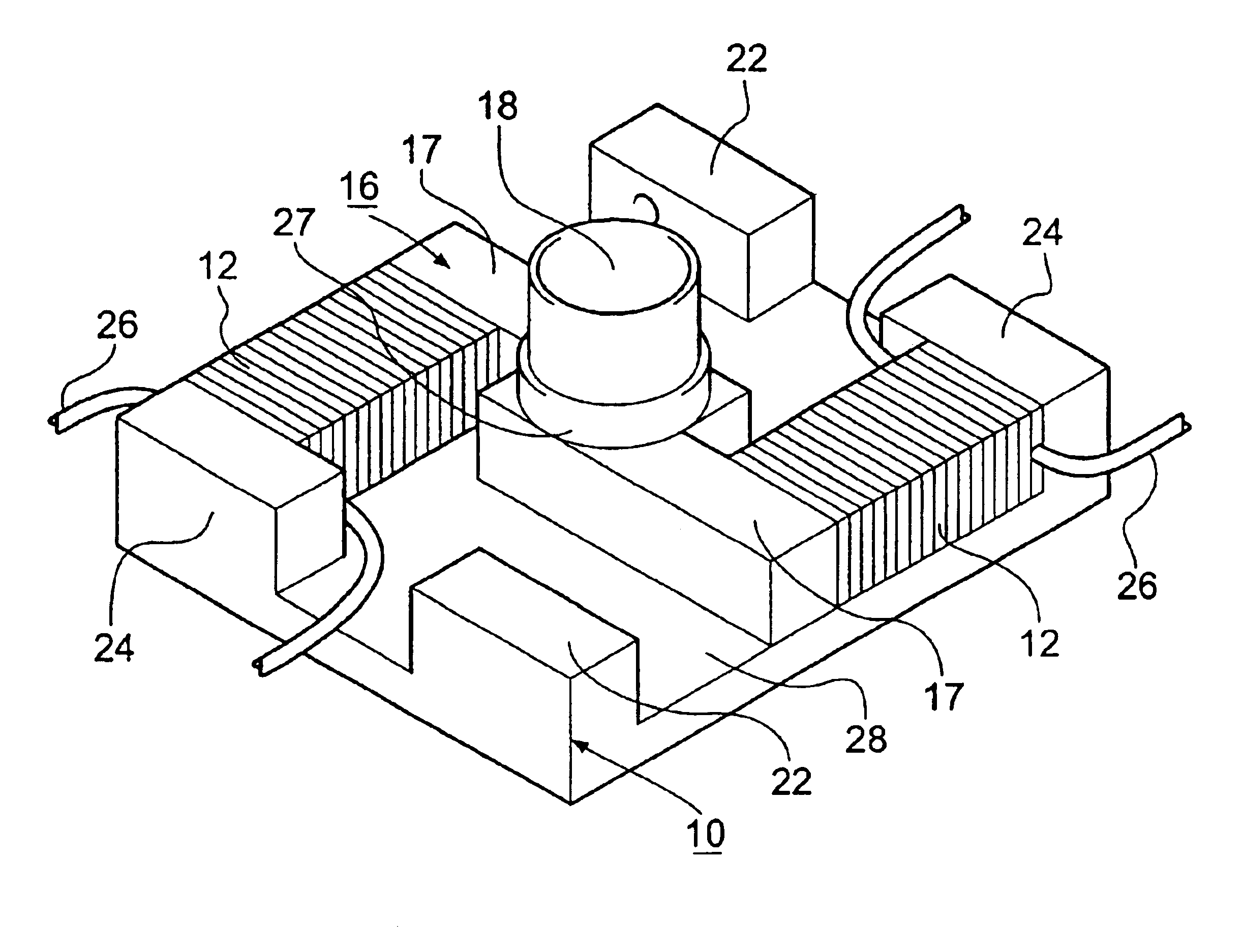
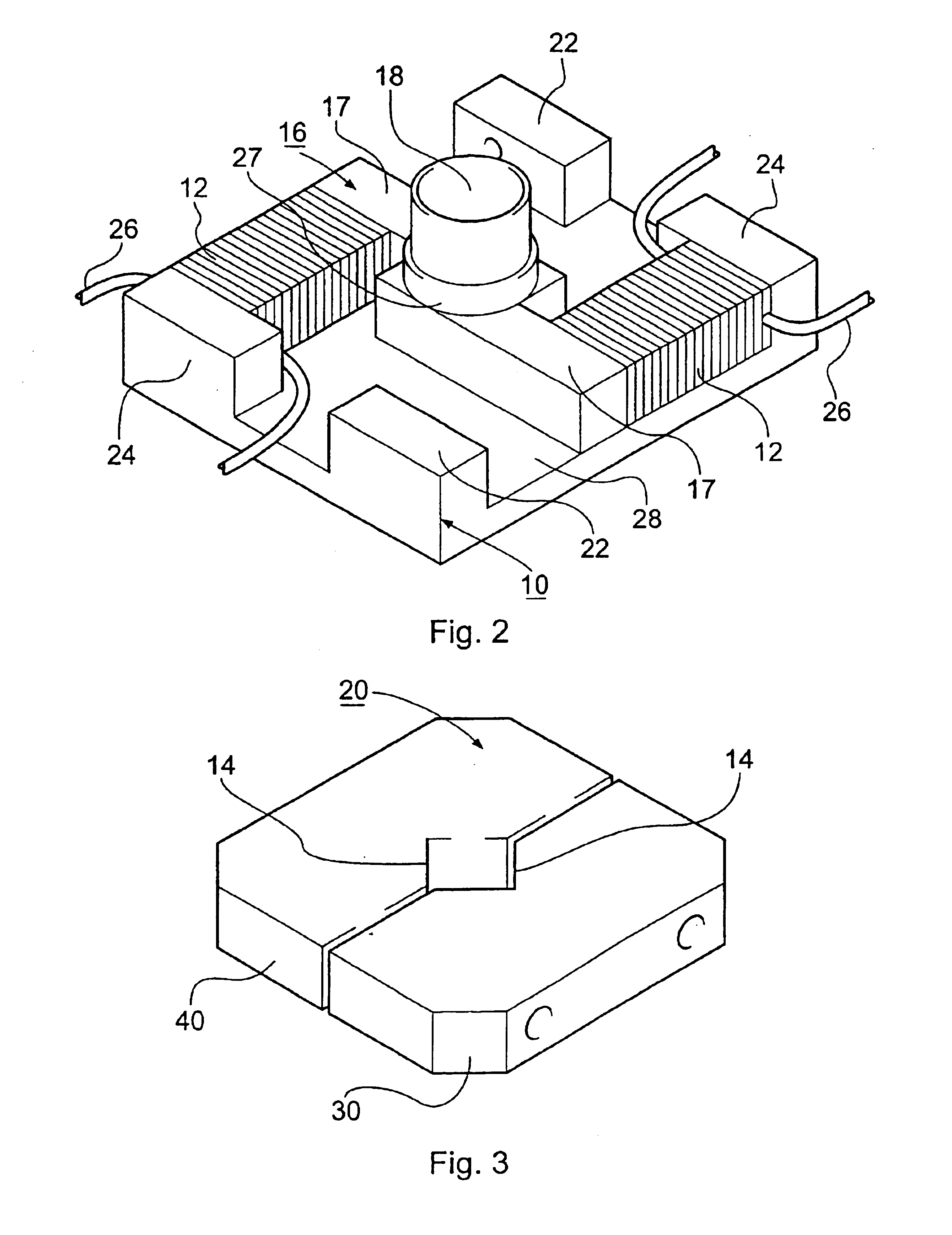
[0040]Some specific parameters are now given for an example device according to the first embodiment. Dimensions: Base plate 20×24×4 mm. Base plate flanges: 7×3.5×4.5 mm, where 4.5 mm is the height dimension, i.e. the height of extension above the upper surface of the base plate. Column height is 6 mm. Column diameter is 5 mm in the upper portion and 6 mm below the abutment lip. The lateral extensions extend 10 mm from the rotation axis of the column and are 3 mm thick and 6 mm high. The piezoelectric actuators are 9 mm long with an area 5×5 mm. The top plate parts 30 and 40 each have external dimensions 24×12×6 mm. The V-groove depths are 3.5 mm and the V-groove angle 90 degrees. The threads and bores are for M2 bolts. The frictional engagement surfaces are coated with molybdenum disulphide, a solid lubricant. The base plate, top plate parts and rotation member are each single pieces of titanium. Titanium is used for its mechanical properties, and owing to it being non-magnetic. Th...


PUM


Abstract

An inertial positioning device comprising: a base plate (10); a top plate (20) for mounting an element to be rotated; a rotation member (16) having a column (18) on which the top plate is mounted in frictional engagement for slip-stick rotational motion; and a pair of piezoelectric actuators (12) each secured to the base plate at one end and to lateral extensions (17) of the rotation member at their other ends. Simultaneous actuation of the piezoelectric actuators rotates the column of the rotation member about its axis. When a suitable asymmetric drive signal is supplied to the piezoelectric actuators, the top plate is rotated by slip-stick motion. The device is compact, has a good load capacity for an inertial motor and is operable in extreme environments such as liquid helium temperatures, high vacuum and high magnetic fields.

Description

BACKGROUND OF THE INVENTION[0001]The invention relates to devices for rotating an object about an axis, more especially to rotation devices that operate by the principle of inertial slip-stick motion.[0002]Rotational positioning devices are in widespread use in diverse industrial and scientific applications. Applications that use rotational positioners include: various forms of microscopy, including scanning probe microscopy, optical microscopy and electron microscopy; sample handling during semiconductor processing; a variety of vacuum applications, including ultra-high-vacuum (UHV) applications; rotation of objects in a magnetic field generated by a conventional or superconducting magnet; and a variety of applications related to rotating samples or other components inside cryostats, including magnet cryostats.[0003]Rotational positioning devices may be based on a number of different classes of design. For example, the devices may be based on stepper motors. Another class of design...

Claims


Application Information

Patent Timeline
Patent Type & Authority Patents(United States)
IPC IPC(8): G12B21/22G12B21/00H01L41/09G01Q10/04H02N2/00H02N2/10H02N2/12
CPCB82Y35/00G01Q10/04H02N2/101
Inventor KARRAI, KHALEDHAINES, MILES
Owner ATTOCUBE SYST AG
Why Eureka
Try Eureka