Modularized cold runner system

A technology of cold runner and fixed mold, which is applied in the field of cold runner injection molding molds, can solve the problems of frequent cleaning of molds, unbalanced mold thermal layout, long mold production cycle, etc., to shorten the product injection molding cycle, reduce Raw material waste and injection pressure and clamping force, effects of avoiding trimming process

Active Publication Date: 2012-12-19
XIAMEN UNIV OF TECH +1
View PDF7 Cites 17 Cited by
  • Summary
  • Abstract
  • Description
  • Claims
  • Application Information

AI Technical Summary

Problems solved by technology

[0002] The injection molding process of low-viscosity two-component materials (such as liquid silicon, etc.) is characterized by low-temperature injection filling and high-temperature vulcanization molding. There are currently a series of defects in the development of its molding molds: ① They are all independently processed and assembled by traditional single parts The method not only makes the mold production cycle long and the cost is high, but also the mold debugging is difficult and the debugging cycle is long; ②There is a large temperature difference between the mold cavity and the material flow channel, and the material must be kept at a low temperature in the flow channel, the traditional method Mold development can easily lead to unbalanced thermal layout of the mold, which makes materials often heat and solidify in the flow channel, which not only leads to frequent cleaning of the mold, low production efficiency, but also brings a series of problems such as material recovery costs and environmental protection; ③ Mold versatility It is not strong enough to be reused conveniently, and for the same family of products, each part requires a set of molds, which leads to high product costs, otherwise it will lead to unbalanced flow, which makes the curing process of the product different at the same time. Various parts produce different pressures, which put forward high requirements on the performance parameters of the molding equipment and the properties of the mold materials, and easily lead to product defects
[0003] At present, there is no related report close to the application of the present invention

Method used


Image

  • Modularized cold runner system
  • Modularized cold runner system
  • Modularized cold runner system

Examples


Embodiment Construction

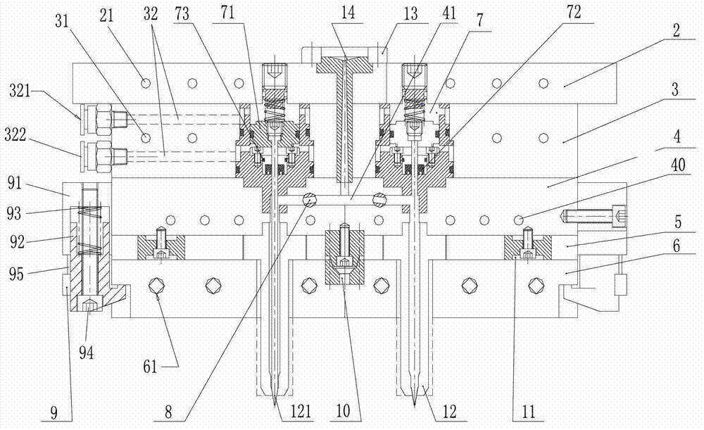
[0030] see figure 1 , the present invention is sequentially provided with a fixed mold base plate 2, a cylinder mounting plate 3, a cold runner plate 4, a heat insulation plate 5, a heating plate 6, a cylinder 7, a fluid modulation device 8, a taper positioning block 10, and a bearing Briquetting block 11 (there are several), water-cooled needle valve nozzle 12 and quick-change fixture 9 etc.

[0031]The fixed mold seat plate 2 is connected with the external frame through a pressing plate. The upper end of the fixed mold base plate 2 is provided with a positioning ring 13, and the fixed mold base plate 2 is provided with a sprue sleeve 14. The sprue sleeve 14 passes through the fixed mold base plate 2 and the cylinder mounting plate 3, and the upper end of the sprue sleeve 14 and the positioning ring Corresponding to 13, the lower end of the sprue sleeve 14 extends into the cold runner plate 4, and the sprue sleeve 14 is provided with a sprue 141. The end of the main channel...


PUM


Abstract

A modularized cold runner system relates to an injection molding die of a colder runner. The system can effectively isolate heat exchange between a high-temperature mold cavity and a low-temperature cold runner system, maintain heat balance of the whole modularized cold runner system, always keep low-temperature flow, prevent materials from being heated and vulcanized in the flow channel, and achieve molding for products without the runner. The system is good in controllability and versatility. The system is provided with, from top to bottom, a stationary mold base plate, a sprue bush, a cylinder installing plate, a cylinder, a cold runner plate, a heat isolation plate, a heating plate, a fluid modulation apparatus, a conicity locating piece, pressure blocks, a water-cooled needle-valve nozzle and a quickly-changed clamp, wherein the stationary mold base plate, the cylinder installing plate, the cold runner plate, the heat isolation plate and the heating plate are sequentially arranged from top to down and fixedly connected through fasteners.

Description

technical field [0001] The invention relates to a cold runner injection molding mold, in particular to a modular cold runner system used in conjunction with a low viscosity two-component material (such as liquid silicon, etc.) cold runner injection molding mold. Background technique [0002] The injection molding process of low-viscosity two-component materials (such as liquid silicon, etc.) is characterized by low-temperature injection filling and high-temperature vulcanization molding. There are currently a series of defects in the development of its molding molds: ① They are all independently processed and assembled by traditional single parts The method not only makes the mold production cycle long and the cost is high, but also the mold debugging is difficult and the debugging cycle is long; ②There is a large temperature difference between the mold cavity and the material flow channel, and the material must be kept at a low temperature in the flow channel, the traditiona...

Claims


Application Information

Patent Timeline
Patent Type & Authority Applications(China)
IPC IPC(8): B29C45/27B29C45/30B29C45/73
Inventor 龚晓叁张记晖葛晓宏易际明石利明
Owner XIAMEN UNIV OF TECH
Why Eureka
Try Eureka