Releasing method and releasing apparatus of work having adhesive tape

a technology of releasing method and releasing apparatus, which is applied in the direction of mechanical apparatus, sleeve/socket joint, layered products, etc., can solve the problems of deformation of dicing adhesive tape, cracking or damage of semiconductor wafers, and delay in releas

Inactive Publication Date: 2005-03-31
NITTO DENKO CORP
View PDF10 Cites 18 Cited by
  • Summary
  • Abstract
  • Description
  • Claims
  • Application Information

AI Technical Summary

Benefits of technology

[0008] The present invention is made in view of the above circumstances, and it is therefore an object of the present invention to provide a releasing method and a releasing apparatus of a work having an adhesive tape for preventing a work such as a semiconductor wafer from being damaged when a back surface polishing process is completed, after a dicing adhesive tape surface joined to cut the wafer into chips (dicin

Problems solved by technology

If the back surface of the dicing adhesive tape is sucked and held on the holding member made of a porous material, a delay of release is generated in a holding region is generated at the time of releasing, and there is a problem that the dicing adhesive tape is

Method used


Image

  • Releasing method and releasing apparatus of work having adhesive tape
  • Releasing method and releasing apparatus of work having adhesive tape
  • Releasing method and releasing apparatus of work having adhesive tape

Examples


Embodiment Construction

[0036] An example of embodiments of the present invention will be explained with reference to the drawings.

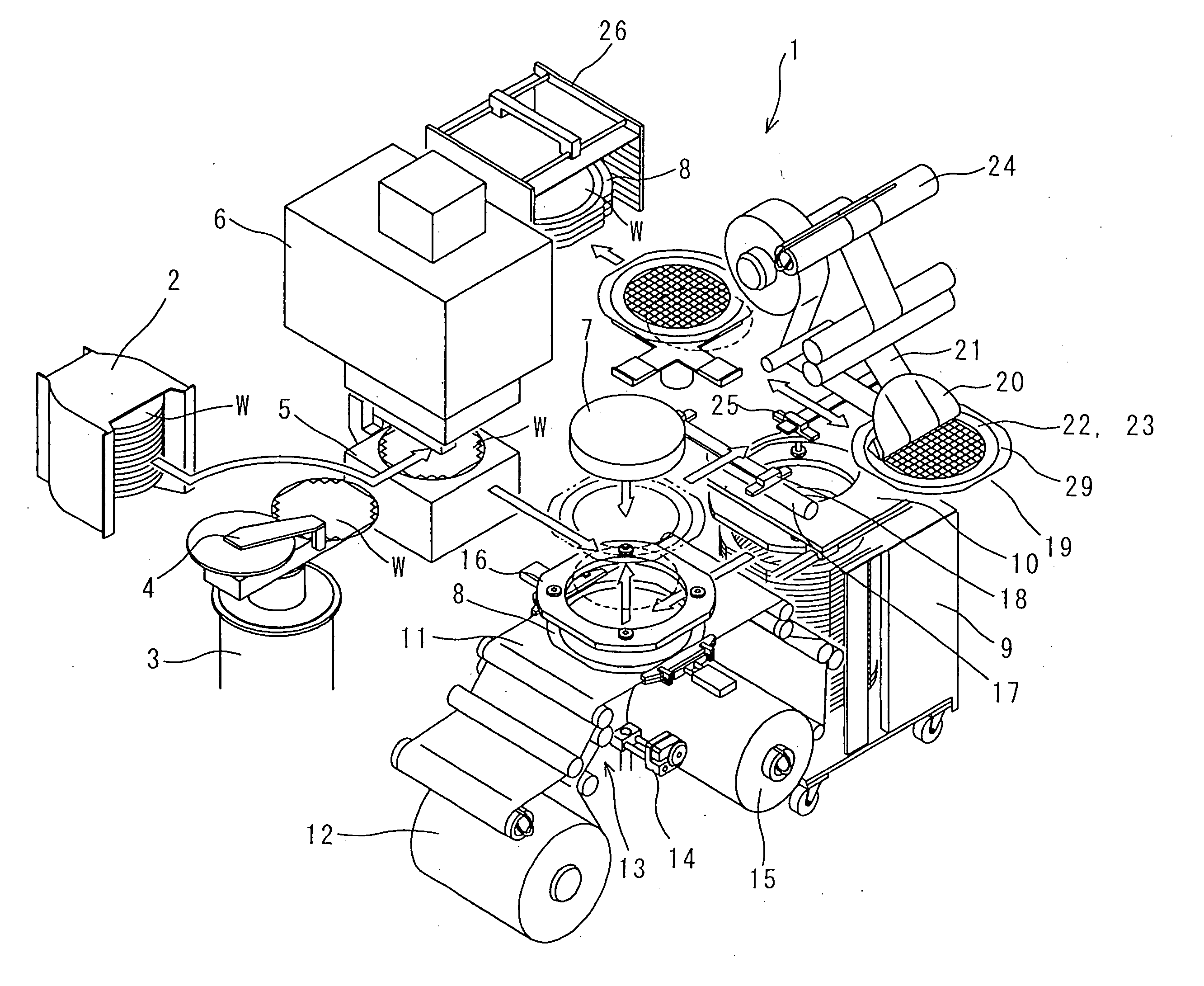
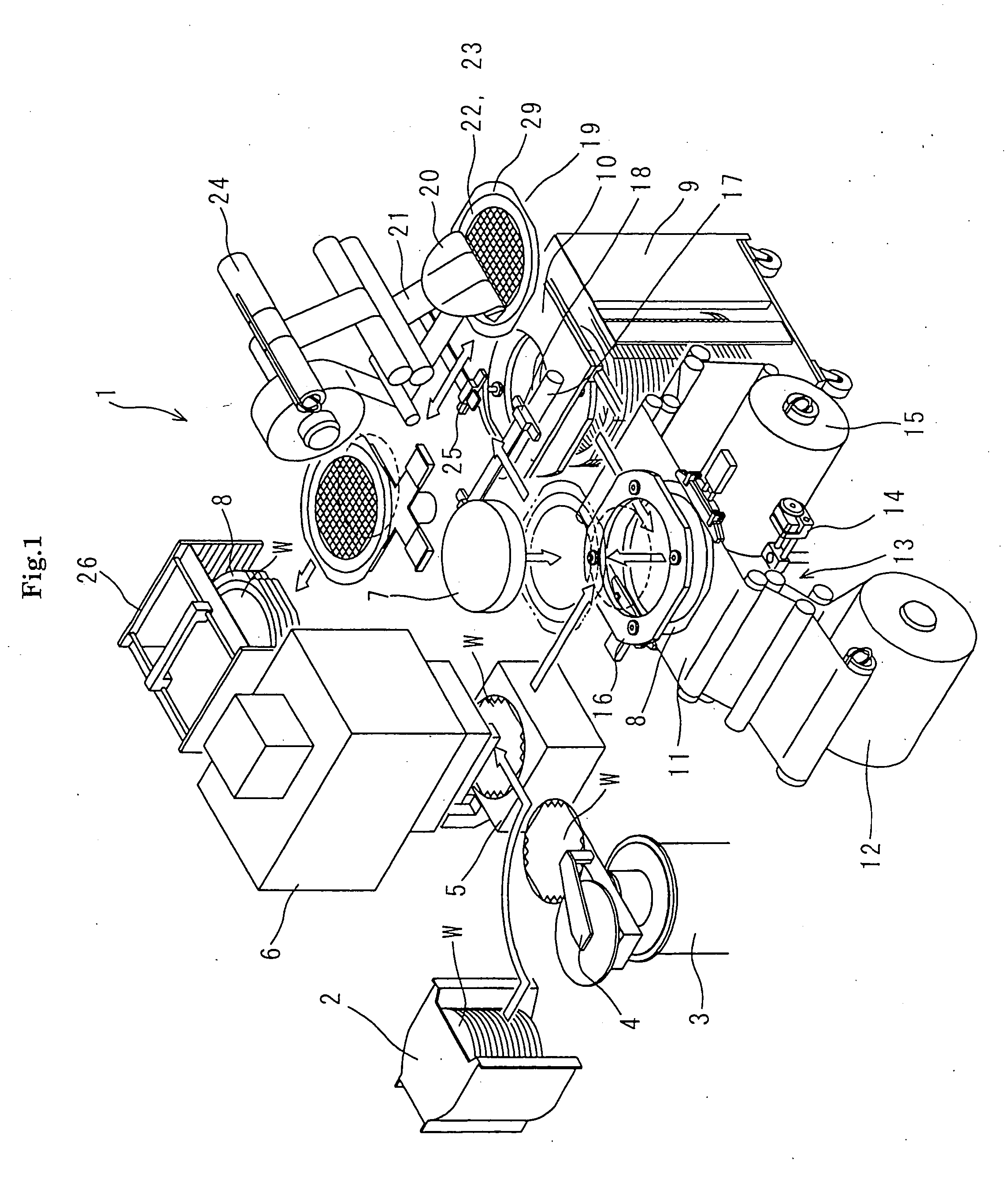
[0037]FIG. 1 is a schematic perspective view showing an essential portion of one example of a semiconductor wafer mount apparatus having one example of embodiments of a releasing apparatus of a work having an adhesive tape according to the present invention.

[0038] As shown in FIG. 1, a semiconductor wafer mount apparatus 1 of the embodiment includes a wafer supply section 2 to which a cassette. A plurality of layers of semiconductor wafers (wafers, hereinafter) W subjected to the back grind process are accommodated in the cassette. The semiconductor wafer mount apparatus 1 also includes a wafer transport mechanism 3 having a robot arm which bends and turns, a wafer pressing mechanism 4 which corrects a warped wafer into a flat surface, an alignment stage 5 which carries out the positioning, an ultraviolet rays irradiation unit 6 for irradiating the surface protecting tape wit...


PUM

PropertyMeasurementUnit
Forceaaaaaaaaaa

Abstract

In a method for releasing a work having an adhesive tape from a holding member which sucks and holds the work having the adhesive tape, the work having the adhesive tape is released from the holding member while supplying a gas which reduces a holding force of the holding member between the holding member and the work having the adhesive tape.

Description

BACKGROUND OF THE INVENTION [0001] (1) Field of the Invention [0002] The present invention relates to a releasing method and a releasing apparatus of a work having an adhesive tape for releasing the work having the adhesive tape from a holding member which sucks and holds the work having the adhesive tape after it is subjected to a predetermined processing. [0003] (2) Description of the Related Art [0004] Conventionally, a surface protecting tape is joined to a surface of a semiconductor wafer formed with a pattern. The surface protecting tape protruding from an outer periphery of the semiconductor wafer is cut out along an outer peripheral edge of the semiconductor wafer, a back surface of the semiconductor wafer is polished in a state in which the entire semiconductor wafer surface is protected by the surface protecting tape, and the semiconductor wafer is thinned (see JP-A 6-302569, for example). [0005] A protecting tape (dicing adhesive tape) is joined (wafer mount) to the semic...

Claims


Application Information

Patent Timeline
IPC IPC(8): H01L21/78B32B1/00H01L21/00H01L21/30H01L21/301H01L21/304H01L21/68H01L21/683
CPCB32B2038/1891H01L21/67092H01L21/67132H01L21/6838Y10T156/17Y10T156/1944Y10S156/941Y10T156/1922Y10T156/1928Y10T156/1978Y10T156/1126Y10T29/49998Y10T29/53191Y10T279/11H01L21/78
Inventor YAMAMOTO, MASAYUKIKANESHIMA, YASUJI
Owner NITTO DENKO CORP
Why Eureka
Try Eureka