Tire with beads designed to ease removal from rim

Inactive Publication Date: 2000-09-12
MICHELIN & CO CIE GEN DES ESTAB MICHELIN
View PDF5 Cites 18 Cited by
  • Summary
  • Abstract
  • Description
  • Claims
  • Application Information

AI Technical Summary

Problems solved by technology

It is well known that if a tire is removed carelessly there may be irreversible damage to the bead (breakage of carcass cords, tearing of the heel of the bead which is usually retained by a hump, etc.) as a result of the localized and high extensile forces imposed during the first phase of the removal.
This substantial and localized offsetting causes a lengthening of the bead wire, and this may lead to irreparable damage to the bead of the tire.
In the most widespread case, that is a bead which is rigid in terms of rotation, the tilti

Method used


Image

  • Tire with beads designed to ease removal from rim
  • Tire with beads designed to ease removal from rim
  • Tire with beads designed to ease removal from rim

Examples


Embodiment Construction

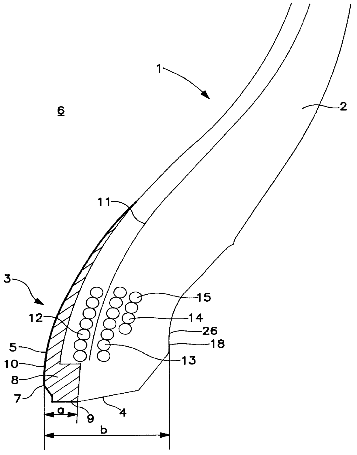
FIG. 1 gives a sectional view of an example of a bead 3 of a tire 1 according to the invention. This bead 3 has a structure which has recently been proposed in patent application EP 0582196. This bead 3 does not have the usual design of carcass folded around a bead wire. Instead, at the anchoring point, the carcass reinforcing elements 11 are arranged in a row. If the arrangement of all these elements 11 in space were to be visualized, they would, within the row, approximately form a partial cone frustum the axis of which coincides with the axis of rotation of the tire. The carcass reinforcing elements 11 are bordered laterally by three piles 12, 13 and 14 of circumferential reinforcing elements 15. These piles are made, for example, by spiral winding. The pile 12 is placed on the same side as the internal cavity 6 of the tire relative to the carcass reinforcing elements 11. The piles 13 and 14 are situated on the outward side of the tire. The rubber blends placed between the piles ...


PUM


Abstract

A tire in which the beads have a slip layer over part of their surface to make them slip more readily over the seats of the wheel rim upon removal after use and thus reduce the risk of damage.

Description

BACKGROUND OF INVENTIONThe present invention relates to tires, and more specifically, to an improved design of tire bead intended to make the tire easier to remove from a rim.The role of tire beads is to "secure" the tire on the wheel rim on which it is mounted. Toward this end, the carcass cords all meet at the bottom part of the bead where they are firmly anchored so that the carcass can withstand tensile loadings in service.In addition to the stresses inherent with the actual use of the tire, the latter needs also to be capable of withstanding an unspecified number of removals followed by refittings for its continuing use.Removal of a tire from its rim involves applying quite a high force to the bead near the flange of the wheel rim or just beyond it. This force is oriented parallel to the axis of rotation and is usually applied by a press to successive portions of the circumference of the bead that correspond to circular arcs of approximately 60 degrees. This is the first phase ...

Claims


Application Information

Patent Timeline
IPC IPC(8): B44D2/00B44D3/00B60C15/00B60C15/024B60C15/06
CPCB60C15/0018B60C15/024B60C15/06Y10T152/10828Y10T152/10846Y10T152/10819B60C15/0603
Inventor COSTA PEREIRA, PEDROPRADELLE, JEAN-JACQUES
Owner MICHELIN & CO CIE GEN DES ESTAB MICHELIN
Why Eureka
Try Eureka