Fluid reservoir for an aerosol generator and aerosol generator comprising the fluid reservoir

a technology of fluid reservoir and generator, which is applied in the direction of inhalator, medical device, other medical devices, etc., can solve the problems of compromising aerosol therapy, affecting the effectiveness of aerosol therapy, and the fluid reservoir is very sensitive to the degree of sensitivity, so as to achieve the effect of preventing reuse of fluid reservoir and simple manner

Inactive Publication Date: 2017-08-17
PARI PHARMA GMBH
View PDF0 Cites 43 Cited by
  • Summary
  • Abstract
  • Description
  • Claims
  • Application Information

AI Technical Summary

Benefits of technology

[0117]The aerosol generator may further comprise a membrane, e.g., a vibratable or oscillatable membrane, for generating an aerosol. The membrane may be arranged in a plane substantially perpendicular to the height direction of the fluid chamber. In this case, the membrane is arranged in horizontal alignment or orientation, i.e., so that the membrane lies in the horizontal plane, when the fluid reservoir is in the upright, i.e., vertical position. In this way, fluid or liquid received in the fluid chamber can be supplied to the membrane of the aerosol generator in a particularly simple manner, e.g., by gravity acting on the fluid or liquid.
[0118]The membrane may be arranged in a plane substantially parallel to the height direction of the fluid chamber. In this case, the membrane is arranged in vertical alignment or orientation, i.e., so that the membrane lies in a vertical plane, when the fluid reservoir is in the upright, i.e., vertical, position.
[0119]The aerosol generator may be a gravity-fed aerosol generator, i.e., the aerosol generator may be configured so that the fluid or liquid received in the fluid chamber is supplied from the fluid chamber through the opening to an aerosol generation portion of the aeroso...

Problems solved by technology

This is because vibrating membrane nebulisers are able to aerosolise essentially all of the liquid filled into the reservoir, whereas jet nebulisers have an inherent residual volume left inside the nebuliser due to droplet impaction and wetting of large internal surface areas from which the recirculating liquid cannot be fully recovered.
However, known retention reservoirs are very sensitive to t...

Method used


Image

  • Fluid reservoir for an aerosol generator and aerosol generator comprising the fluid reservoir
  • Fluid reservoir for an aerosol generator and aerosol generator comprising the fluid reservoir
  • Fluid reservoir for an aerosol generator and aerosol generator comprising the fluid reservoir

Examples


Embodiment Construction

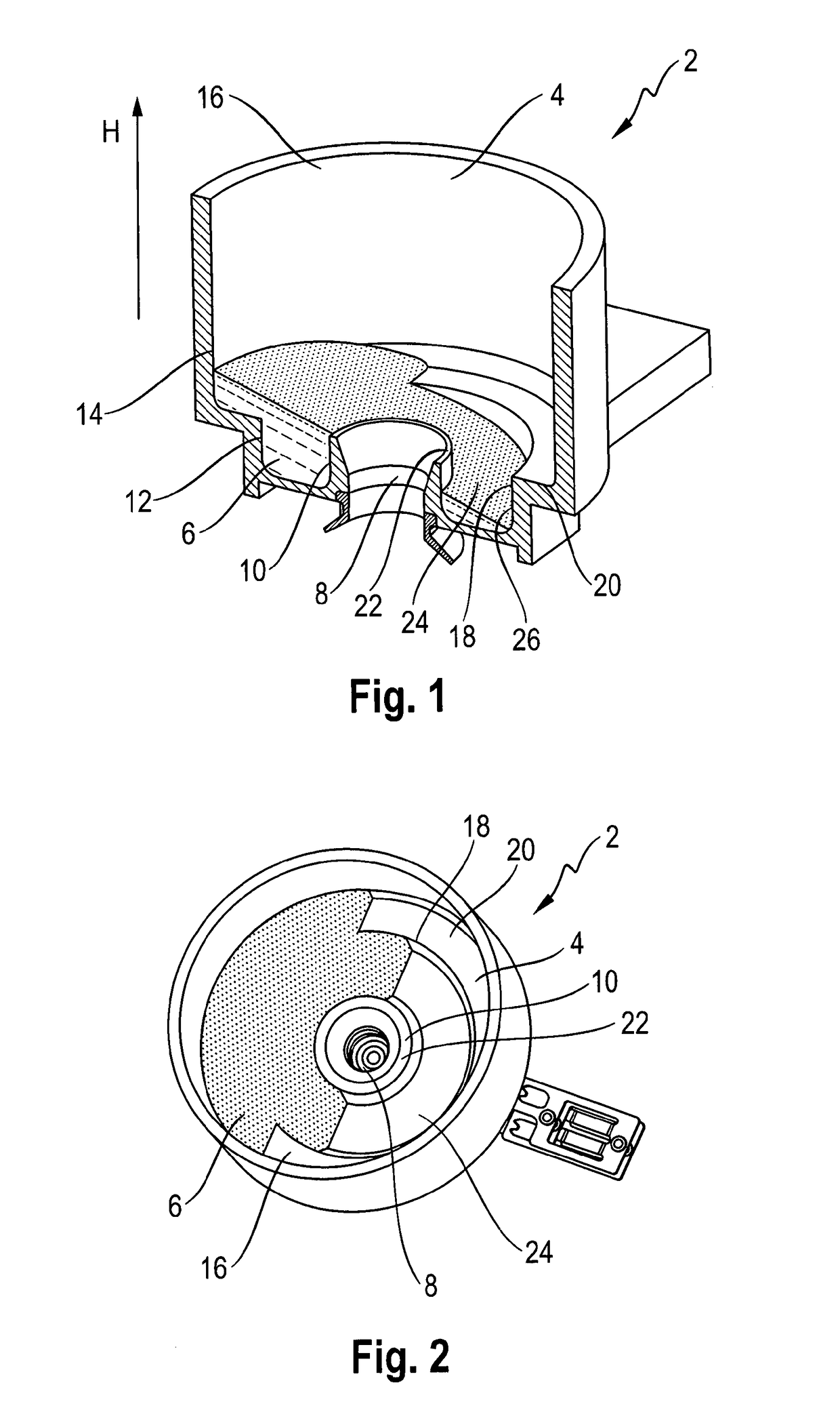
[0139]FIG. 1 shows a schematic longitudinally cut cross-sectional view of a fluid reservoir 2 according to a currently preferred embodiment of the present invention. FIG. 2 shows a schematic perspective top view of the fluid reservoir 2 shown in FIG. 1.

[0140]The fluid reservoir 2 comprises a fluid chamber 4 for receiving a fluid 6 to be aerosolised and an opening 8 for guiding the fluid 6 received in the fluid chamber 4 outside the fluid chamber 4. Further, the fluid reservoir 2 comprises a collar portion 10 surrounding the opening 8 and extending into the fluid chamber 4.

[0141]A first portion 12 of the fluid chamber 4 extends along the length of the collar portion 10 in a height direction H of the fluid chamber 4. A second portion 14 of the fluid chamber 4 is arranged adjacent to, i.e., above, the first portion 12 in the height direction H of the fluid chamber 4. A lateral extension, i.e., an inner diameter, of the first portion 12 in the directions perpendicular to the height dire...


PUM


Abstract

The invention relates to a fluid reservoir (2) for an aerosol generator (50), the fluid reservoir (2) comprising a fluid chamber (4) for receiving a fluid (6), an opening (8) for guiding the fluid (6) received in the fluid chamber (4) outside the fluid chamber (4), and a collar portion (10) surrounding the opening (8) and extending into the fluid chamber (4). A first portion (12) of the fluid chamber (4) extends along the length of the collar portion (10) in a height direction (H) of the fluid chamber (4), A second portion (14) of the fluid chamber (4) is arranged adjacent to the first portion (12) in the height direction (H) of the fluid chamber (4). A lateral extension of the first portion (12) in the directions perpendicular to the height direction (H) of the fluid chamber (4) is smaller than a lateral extension of the second portion (14) in the directions perpendicular to the height direction (H) of the fluid chamber (4). Further, the invention relates to a fluid reservoir (2′) for an aerosol generator (50), the fluid reservoir (2′) comprising a fluid chamber (4′) for receiving a fluid (6′), an opening (8′) for guiding the fluid (6′) received in the fluid chamber (4′) outside the fluid chamber (4′), a recess (9) arranged at least partly below the opening (8!) in a height direction (H) of the fluid chamber (4′), and a cover member (30′) which releasably or permanently seals the recess (9). Moreover, the invention relates to an aerosol generator (50) comprising the fluid reservoir (2, 2′).

Description

FIELD OF THE INVENTION[0001]The invention relates to a fluid reservoir for an aerosol generator, the fluid reservoir comprising a fluid chamber for receiving a fluid and an opening for guiding the fluid received in the fluid chamber outside the fluid chamber. Further, the invention relates to an aerosol generator comprising the fluid reservoir.BACKGROUND ART[0002]Aerosols for therapeutic purposes are generated and delivered to a desired location within a user's or patients body with aerosol delivery devices. A fluid or liquid (i.e., medicament) to be aerosolised or nebulised is received in a fluid reservoir, supplied from the fluid reservoir to an aerosol generator of the aerosol delivery device and aerosolised or nebulised by the aerosol generator. The resultant aerosol is supplied to the user or patient.[0003]The requirements placed on the aerosol delivery device arise from the treatment to be performed with the aerosols. One of these requirements concerns dosage accuracy and prec...

Claims


Application Information

Patent Timeline
IPC IPC(8): A61M15/00
CPCA61M15/009A61M15/0005A61M2207/00A61M2205/3334A61M2205/21A61M11/005A61M15/0065A61M15/0085A61M2202/04A61M2202/0468A61M2205/273A61M2205/276A61M2205/8206A61M15/0043B05B17/0676B05B17/0646
Inventor GALLEM, THOMASHETZER, UWEKNOCH, MARTINNEUNER, MICHAEL
Owner PARI PHARMA GMBH
Why Eureka
Try Eureka