

Needleless syringe for the delivery of therapeutic agents
a technology of needleless syringes and therapeutic agents, which is applied in the field of needleless syringes, can solve problems such as accelerating the delivery of therapeutic particles
- Summary
- Abstract
- Description
- Claims
- Application Information
AI Technical Summary
Benefits of technology
Problems solved by technology
Method used
Image

Examples
first embodiment
[0085]Turning now to FIG. 5A, a syringe 55 according to the present invention will be described. The syringe 55, whose approximate dimensions are indicated in FIG. 5A, includes a reservoir 58 that is initially at atmospheric pressure, and a particle dose 60. The particle dose 60 comprises an upstream membrane 62 and a downstream membrane 64, containing the particle dose therebetween. The particle dose 60 is positioned in the upstream end 65 of the tubular nozzle 67 such that its upstream membrane 62 is directly adjacent to the reservoir 58. The upstream membrane 62 is designed to support the pressure differences between the reservoir 58 and the tubular nozzle 67. The triggering assembly of the syringe 55 additionally comprises a gas reserve 66 containing a high pressure inert gas 68 positioned upstream from the reservoir 58, as well as a release valve 70, separating the reservoir 58 and the gas reserve 66.
[0086]It is to be noted that the downstream end 56 of the nozzle 67 is enlarge...
fourth embodiment
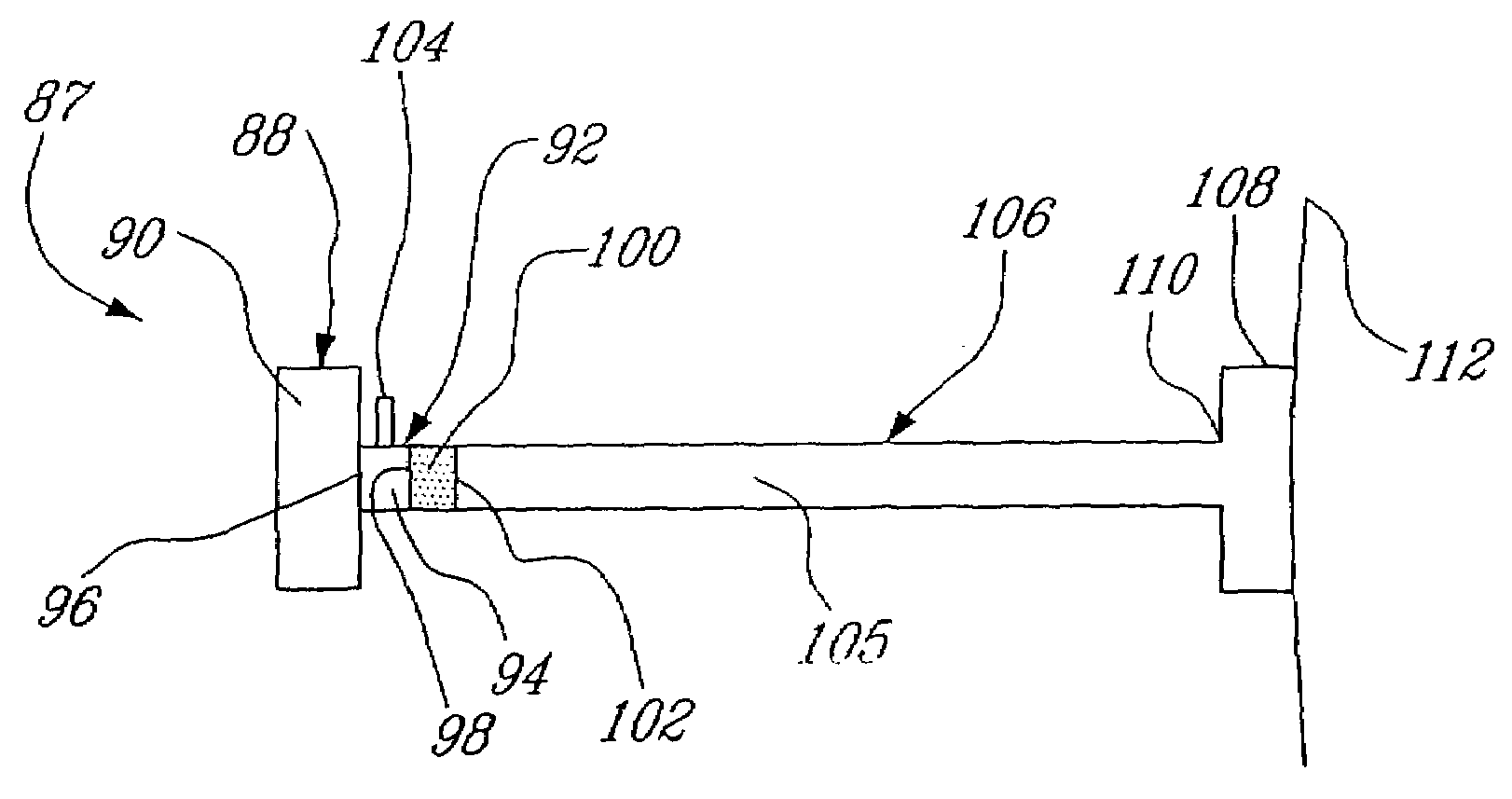
[0108]FIG. 8 schematically illustrates the various parts of a gas compression needleless syringe 113 according to the present invention. The triggering assembly of the syringe 113 comprises a reserve 114 filled with compressed air or any other compressed gas 116, that is mounted upstream from a reservoir 118. The reservoir 118 comprises a first chamber 120 that is filled with air or an inert gas 122 at atmospheric pressure and a second chamber 124, filled with an inert gas 126 at atmospheric pressure.
[0109]A piston 128 is positioned between the first chamber 120 and the second chamber 124. Additionally, a release valve 130 is positioned between the reserve 114 and the first chamber 120.
[0110]The downstream end 132 of the second chamber 124 comprises a membrane 134 against which is placed a particle dose 136. A second membrane 137 encloses the particle dose 136. The needleless syringe 113 additionally comprises a tubular nozzle 138 and a spacer / silencer 140 placed against the target ...
fifth embodiment
[0115]FIG. 9 schematically illustrates the various parts of a gas compression syringe 143 in accordance with the present invention.
[0116]This approach eliminates all sources of compressed gas. The triggering assembly of the syringe 143 includes a cylindrical reservoir 144 that comprises a downstream chamber 146, filled with an inert gas 148 at atmospheric pressure or above, and an upstream chamber 150 open to the atmosphere. A piston 152 separates the upstream chamber 150 from the downstream chamber 146. A compression spring 154 (shown in its compressed state) is positioned in the upstream chamber 150 and is connected to the piston 152.
[0117]The syringe 143 additionally comprises a tubular nozzle 158 mounted to the downstream end of the cylindrical reservoir 144. A particle dose 160, comprising an upstream membrane 156 and a downstream membrane 162, is positioned at the upstream end of the tubular nozzle 158. The tubular nozzle 158 is in contact with the chamber 146.
[0118]The exit 1...
PUM
 Abstract
Description
Claims
Application Information