Engine and diffuser for use with a needle-less injector

a technology of injector and engine, which is applied in the direction of medical syringes, automatic syringes, intravenous devices, etc., can solve the problems of high production cost of traditional needle injectors, such as hypodermic syringes, and difficult use of pre-packaged medication doses, so as to avoid potential injury and mitigate the effect of kickback

Inactive Publication Date: 2004-11-30
PENJET CORP
View PDF172 Cites 36 Cited by
  • Summary
  • Abstract
  • Description
  • Claims
  • Application Information

AI Technical Summary

Benefits of technology

In another embodiment of the instant invention, a diffuser suitable for use with a needle-less injector includes an unobstructed air passage that may further include aerodynamic fins. The aerodynamic fins facilitate in the creation and maintenance of air flow with negligible back pressure when compressed gas is forced through the unobstructed air passage of the diffuser.
Several mechanisms act to mitigate the kickback associated with releasing compressed gas from the engine housing. The grips on the valve body are operatively coupled with the locking ring on the exterior surface of the diffuser prior to administration of an injection, and the retainer hooks on the retainer hook mechanisms operatively lock at each successive saw tooth of the latch retainer mechanisms during administration of an injection. Such safety features not only function to avoid potential injury, but further ensure proper delivery of fluid through an injection surface.

Problems solved by technology

In addition, the traditional method of intradermal injections requires actual physical contact and penetration of a needle through the skin surface of the patient, which can be painful for the patient.
Traditional needle injectors, such as hypodermic syringes, are also expensive to produce and difficult to use with prepackaged medication doses.
Needle injectors also suffer from increased danger of contamination exposure to health care workers administering the injections, and to the general public when such injectors are not properly disposed of.
However, not only are conventional jet injectors cumbersome and awkward, but, existing conventional jet injectors are only capable of subcutaneous delivery of a medication beneath the skin layers of a patient.
Conventional jet injectors are also somewhat dangerous to use, since they can be discharged without being placed against the skin surface.
In addition, jet injectors that have not been properly sterilized are notorious for creating infections at the injection site.
Moreover, if a jet injector is not positioned properly against the injection site, the injection can result in wetting on the skin surface.
Problems associated with improper dosage amounts may arise as well, if some portion of the fluid intended for injection remains on the skin surface following an injection, having not been properly injected into and / or through the skin surface.
It should be noted, however, that compression spring propelled jet injectors do not offer linear delivery speeds (constant speed of the fluid being injected).
In addition to this problem, spring propelled jet injectors with weak (e.g., deteriorated) springs often slow fluid delivery speed down while an injection is being administered, resulting in improper fluid penetration.
Reduced speed of the fluid can cause improper dosing and bruising at the injection site when the injection surface is the skin of a human recipient.
In a jet injector, if the inert gas is not quickly and properly expelled, fluid may be improperly injected, as with those devices employing a compression spring.
Difficulties arise in the need to maintain tight tolerances on the breakable member, since minor changes in thickness can dramatically effect the pressure needed to deploy the gas from the gas chamber of the device.
In addition, the broken shards of the breakable member are ejected at high speed when the gas is expelled and these shards can occasionally jam between the plunger driver and the housing, thereby preventing proper operation of the needle-less injector.
Attempts to prevent small shards from being formed would obviate some of this potential, but tend to make activation of the device more difficult.
Gas power sources for needle-less injectors that employ either pop valves or breakaway tab valves to release the inert gas stored in their respective gas chambers, however, may only be opened once, thereby presenting difficulty with regard to quality control testing measures.
Further, operation of many injectors requires a user to depress a trigger, relying mainly on resistance force from the injection surface to initiate an injection.
Where the underlying surface is sensitive, applying such pressure may not be advantageous.
Further, if the injection surface is slippery such a device may slide out of place during an injection rendering its use potentially injurious and possibly resulting in improper fluid delivery.
However, the use of channels in a diffuser may result in excessive back pressure upon deployment of gas from the engine.
Consequentially, optimal gas flow may not be achieved, and the injector may not operate in the most efficient manner possible.
Suboptimal gas flow may result in a comparatively slower injection; shallower liquid penetration into the patient; and moderate pain upon administration of an injection.
Moreover, upon mechanical interaction of the grips and diffuser, an unpleasant "clicking" sound may be heard.

Method used


Image

  • Engine and diffuser for use with a needle-less injector
  • Engine and diffuser for use with a needle-less injector
  • Engine and diffuser for use with a needle-less injector

Examples


Embodiment Construction

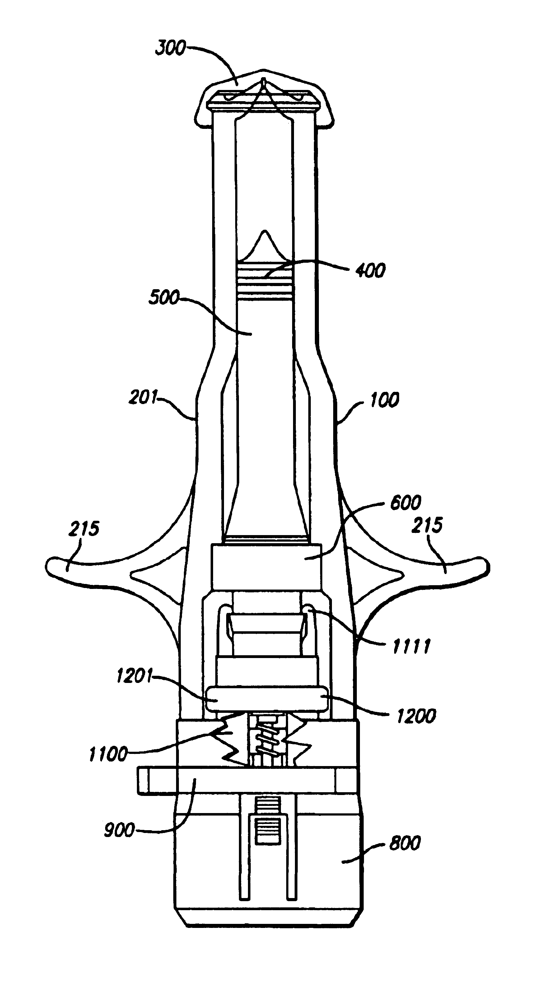
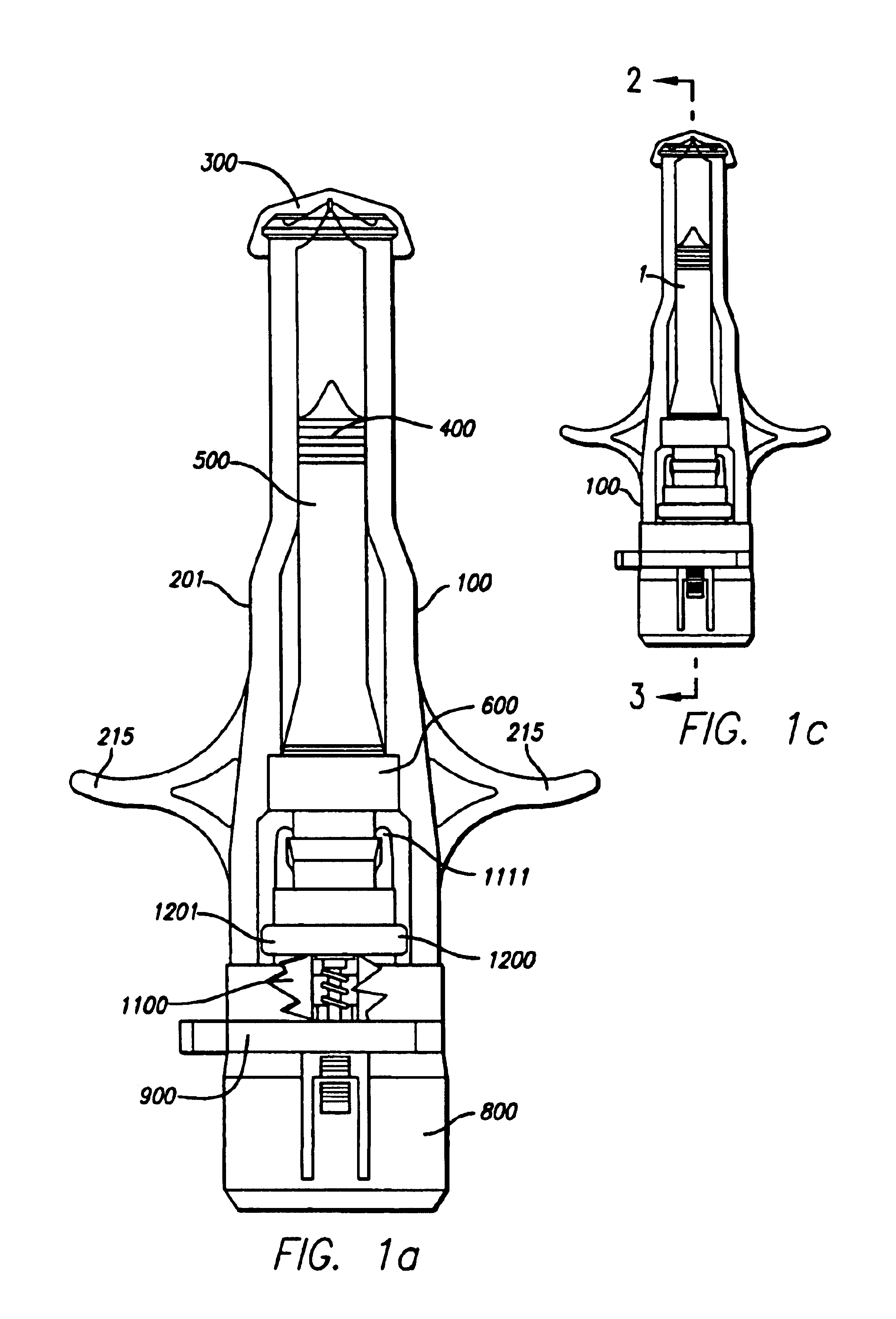
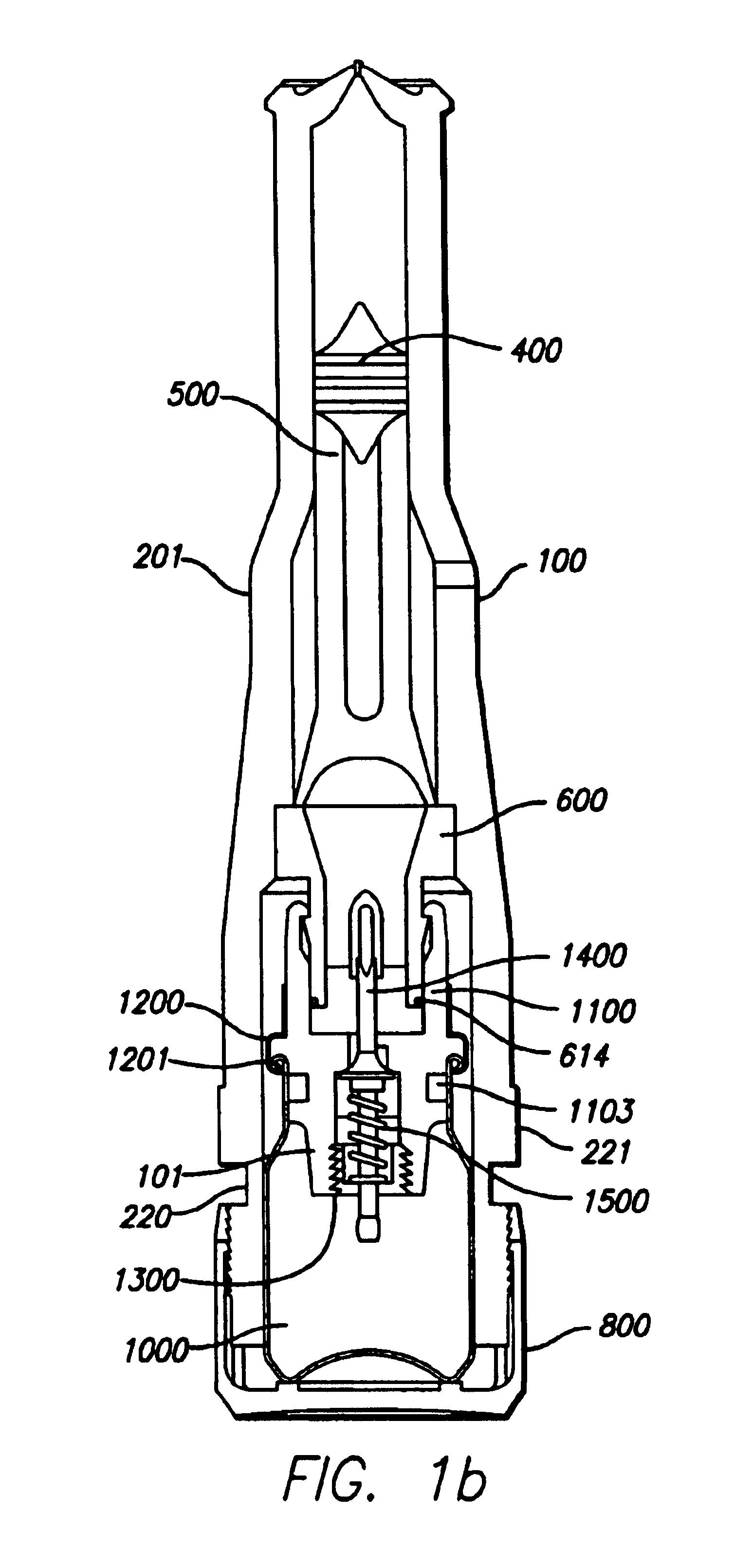
Operation of a Needle-Less Injector

Prior to use, a needle-less injector is assembled in accordance with the instant invention, all elements thereof being gamma sterilized with the exception of the engine assembly. The engine assembly is checked for quality control purposes by opening and closing the valve, and thereafter the engine housing is filled with a suitable compressed gas. The interior portion of the housing between the proximate end of the housing and the proximate end of the plunger is then filled with, in this example, 0.5 ml. of fluid. The needle-less injector is then assembled and stored for a prolonged period of time.

When ready for use (see FIG. 1a), the ampoule cap is removed from the proximate end of the housing by the user. Subsequently, the user also removes the safety clamp by bending and / or distorting the clamp. The user is performing self-administration of an injection and elects to employ the following configuration: the user's index and middle fingers are plac...


PUM


Abstract

A needle-less injector suitable for injecting fluid through a surface includes a housing, a driver, an engine and a trigger. The housing contains a fluid and the engine contains a compressed gas. Upon application of sufficient force to the trigger, the compressed gas is released from the engine forcing the driver through the interior of the housing, expelling the fluid from the housing at a speed sufficient to pierce an injection surface. An aerodynamic diffuser maximizes air flow to the driver, allowing greater injection speed and mitigating pain associated with receiving an injection. Use of the injector is both silent and easy to activate, owing to an O-ring included about the circumference of the exterior of a diffuser operating within the engine. Further, the engine has safety features preventing a portion thereof from separating from the device under elevated temperatures and similar conditions. Engine leakage is obviated by the inclusion of a leakage ring therein.

Description

This invention relates to needle-less injectors, and, in particular, to engine and diffuser assemblies for use with modular gas-pressured needle-less injectors and methods of performing needle-less injections using the same.Traditionally, fluids such as medications are injected into patients, either subdermally or intradermally, using hypodermic syringe needles. The body of the syringe is filled with the injectable fluid and, once the needle has pierced the patient's skin, the syringe plunger is depressed so as to expel the injectable fluid out of an opening in the needle. The person performing the injection is usually a trained medical services provider, who manually inserts the hypodermic needle between the layers of a patient's skin for an intradermal injection, or beneath the skin layers for a subcutaneous injection.Intradermal or subdermal delivery of a medication through the use of a hypodermic needle requires some skill and training for proper and safe administration. In addi...

Claims


Application Information

Patent Timeline
Patent Type & Authority Patents(United States)
IPC IPC(8): A61M5/30A61M5/20
CPCA61M5/30A61M5/2053A61M2005/2073
Inventor CASTELLANO, THOMAS P
Owner PENJET CORP
Why Eureka
Try Eureka