Method and system for thermal imaging having a selective temperature imaging mode

a thermal imaging and selective technology, applied in the field of portable thermal imaging cameras, can solve the problems of limited dynamic range, limited lens size, sensor saturation,

Active Publication Date: 2008-01-22
E D BULLARD
View PDF20 Cites 43 Cited by
  • Summary
  • Abstract
  • Description
  • Claims
  • Application Information

AI Technical Summary

Problems solved by technology

Of course, the size of the lens is limited by weight and costs considerations.
In the early development of thermal imaging cameras, there was a limited dynamic range in that, when using the camera in an environment with extremely high temperatures, such as those encountered in a structure fire, the sensor would become saturated.
As a result, it was difficult to identify fire conditions and “hot spots” in the thermal image with much precision.

Method used


Image

  • Method and system for thermal imaging having a selective temperature imaging mode
  • Method and system for thermal imaging having a selective temperature imaging mode
  • Method and system for thermal imaging having a selective temperature imaging mode

Examples


Embodiment Construction

[0026]The present invention is a method for operating a thermal imaging camera for selective temperature imaging, and a thermal imaging system having a selective temperature imaging mode.

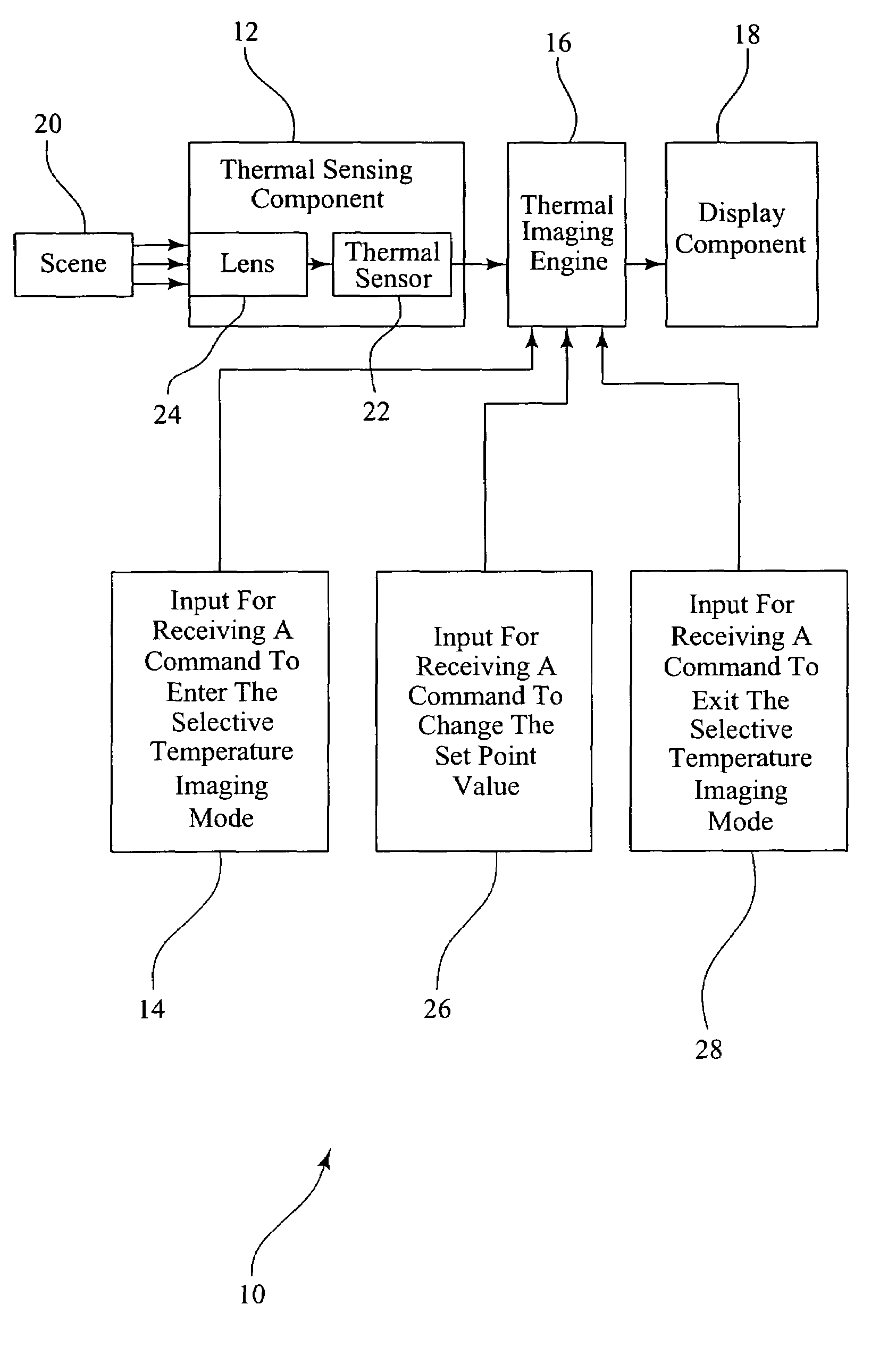
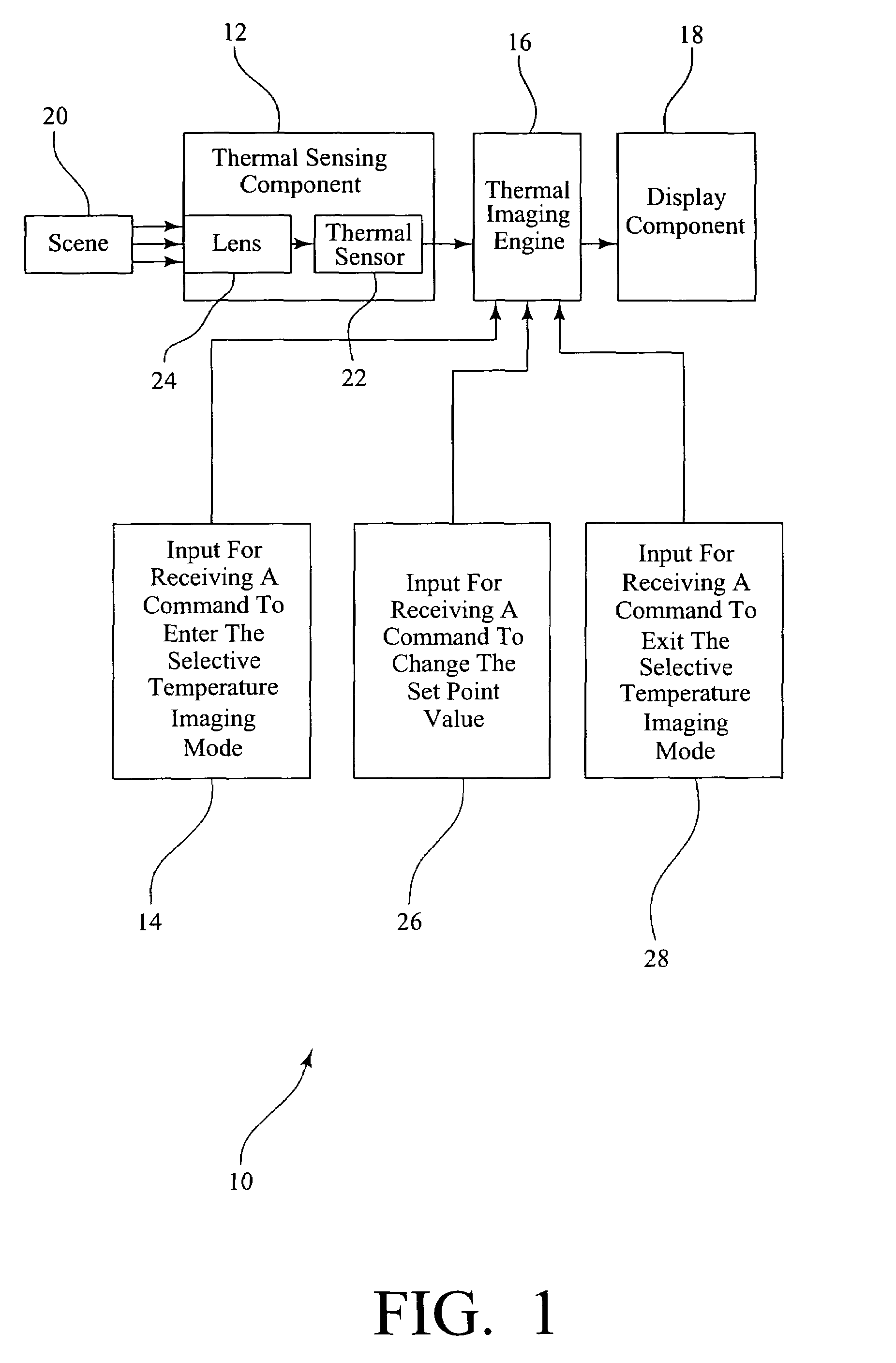
[0027]FIG. 1 is a block diagram of an exemplary thermal imaging system 10 having a selective temperature imaging mode according to the invention. The exemplary thermal imaging system generally includes a thermal sensing component 12, an input 14 for receiving a command to enter a selective temperature imaging mode, a thermal imaging engine 16, and a display component 18. In normal use, the thermal sensing component 12 acquires thermal image data for a scene 20, the thermal imaging engine 16 processes the thermal image data to produce a thermal image having “hot colorization”, as described above, and the thermal image is then displayed on the display component 18. Preferably, the thermal sensing component 12 has a thermal sensor 22 and a lens 24 for focusing infrared radiation from the scene 20 onto ...


PUM


Abstract

The present invention is a method for operating a thermal imaging camera for selective temperature imaging, and a thermal imaging system having a selective temperature imaging mode. When first entering the selective temperature imaging mode of operation, the system and method automatically determine the hottest area in a scene and display it in a predetermined hue. The remainder of the scene is displayed in grayscale. The method and system allow further adjustment of the set point of the selective temperature imaging mode, and display portions of the scene as hot as or hotter than the set point value in gradient shades of the predetermined hue.

Description

CROSS-REFERENCE TO RELATED APPLICATIONS[0001]This application claims the benefit of U.S. Provisional Application No. 60 / 601,017, filed Aug. 12, 2004, the entire disclosure of which is incorporated herein by reference.BACKGROUND OF THE INVENTION[0002]The present invention relates to a portable thermal imaging camera, a device that is commonly used by firefighters and other rescue personnel to identify the seat of a fire from outside of a burning structure, to identify fire conditions within a burning structure hidden by heavy smoke, and / or to identify victims trapped within a burning structure.[0003]Modern thermal imaging cameras, also referred to as thermal imagers, were introduced to firefighters in the mid-1990's. Originally developed for military applications, thermal imaging cameras quickly proved to be a valuable fire-fighting tool, essentially allowing firefighters to “see” in dark, smoke-filled and other extreme environments.[0004]Thermal imaging cameras are now used by firef...

Claims


Application Information

Patent Timeline
Patent Type & Authority Patents(United States)
IPC IPC(8): H01L31/00
CPCG02B23/12
Inventor KING, JOHN H.
Owner E D BULLARD
Why Eureka
Try Eureka