Apparatus, system, and method for maximizing power system holdup time during loss of input power

a technology of power system and holdup time, applied in the direction of power supply for data processing, emergency power supply arrangement, transportation and packaging, etc., can solve the problems of data loss, battery may not be able to provide full amperage power, etc., and achieve the effect of maximizing the power system holdup tim

Inactive Publication Date: 2008-01-22
GOOGLE LLC
View PDF2 Cites 17 Cited by
  • Summary
  • Abstract
  • Description
  • Claims
  • Application Information

AI Technical Summary

Benefits of technology

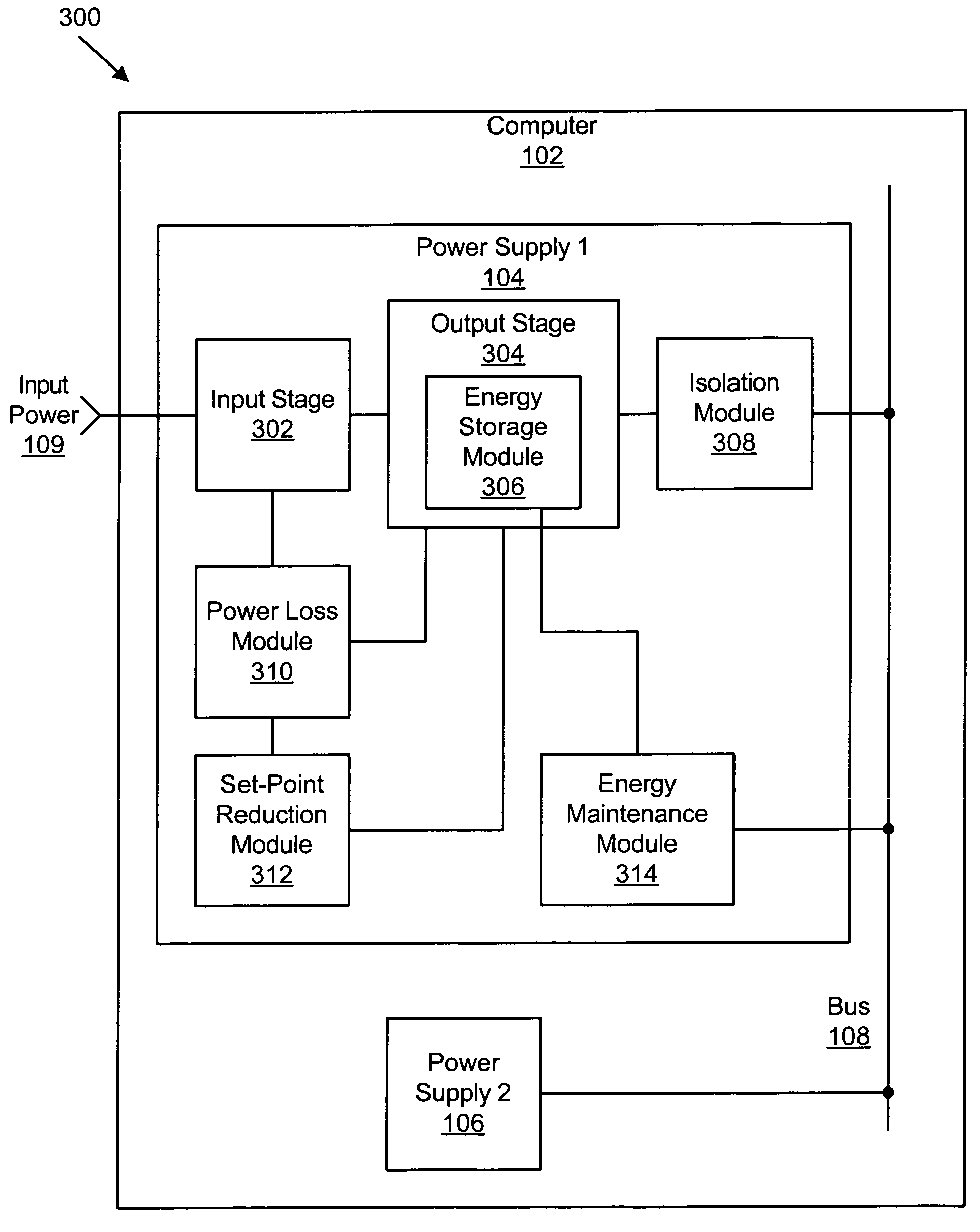
[0021]The apparatus to maximize power system holdup time during loss of input power is provided with a logic unit containing a plurality of modules configured to functionally execute the necessary steps of detecting loss of power transmitting capacity of an input stage to an output stage of a power supply feeding a bus, reducing voltage of the output stage, and preventing energy flow from the bus to the power supply. These modules in the described embodiments include an energy storage module that delivers energy from an output stage of a first power supply to a bus. A power loss module is included that detects loss of power transmitting capability from an input stage of the first power supply to the output stage of the first power supply. A set-point reduction module is included that reduces an output voltage of the first power supply in response to the power loss module detecting loss of power transmitting capability. An isolation module is included that prevents energy flow from the energy storage module to the bus when the output voltage of the first power supply is lower than a voltage on the bus sustained by a second power supply.
[0024]A system of the present invention is also presented for maximizing power system holdup time during loss of input power. The system may be embodied by a bus and a first power supply connected to the bus. The first power supply includes an energy storage module that delivers energy from an output stage of the first power supply to the bus. The first power supply includes a power loss module that detects loss of power transmitting capability from an input stage of the first power supply to the output stage of the first power supply. The first power supply includes a set-point reduction module that reduces an output voltage of the first power supply in response to the power loss module detecting loss of power transmitting capability. The first power supply also includes an isolation module that prevents energy flow from the energy storage module to the bus when the output voltage of the first power supply is lower than a voltage on the bus. The system also includes a second power supply connected to the bus configured to sustain the voltage on the bus when the isolation module prevents energy flow from the energy storage module to the bus.
[0027]An apparatus of the present invention is also presented for maximizing power system holdup time during loss of input power. The apparatus in the disclosed embodiments substantially includes the means necessary to carry out the functions presented above with respect to the operation of the described apparatus and system. In one embodiment, the apparatus includes means for delivering energy from an output stage of a first power supply to a bus. The apparatus includes means for detecting loss of power transmitting capability from an input stage of the first power supply to the output stage of the first power supply. The apparatus includes means for reducing an output voltage of the first power supply in response to detecting loss of power transmitting capability. The apparatus also includes means for preventing energy flow from the output stage of the first power supply to the bus when the output voltage of the first power supply is lower than a voltage on the bus sustained by a second power supply.

Problems solved by technology

When a computer system loses power, data may be lost.
In many situations, however, batteries may not be able to provide power at full amperage as may be required to save critical data.

Method used


Image

  • Apparatus, system, and method for maximizing power system holdup time during loss of input power
  • Apparatus, system, and method for maximizing power system holdup time during loss of input power
  • Apparatus, system, and method for maximizing power system holdup time during loss of input power

Examples


Embodiment Construction

[0040]Many of the functional units described in this specification have been labeled as modules, in order to more particularly emphasize their implementation independence. For example, a module may be implemented as a hardware circuit comprising custom VLSI circuits or gate arrays, off-the-shelf semiconductors such as logic chips, transistors, or other discrete components. A module may also be implemented in programmable hardware devices such as field programmable gate arrays, programmable array logic, programmable logic devices or the like.

[0041]Modules may also be implemented in software for execution by various types of processors. An identified module of executable code may, for instance, comprise one or more physical or logical blocks of computer instructions which may, for instance, be organized as an object, procedure, or function. Nevertheless, the executables of an identified module need not be physically located together, but may comprise disparate instructions stored in d...


PUM


Abstract

An apparatus, system, and method are disclosed for maximizing power system holdup time during loss of input power. An energy storage module is included to deliver energy from an output stage of a first power supply to a bus. A power loss module is included to detect loss of power transmitting capability from an input stage of the first power supply to the output stage of the first power supply. A set-point reduction module is included to reduce an output voltage of the first power supply in response to the power loss module detecting loss of power transmitting capability. An isolation module is included to prevent energy flow from the energy storage module to the bus when the output voltage of the first power supply is lower than a voltage on the bus sustained by a second power supply.

Description

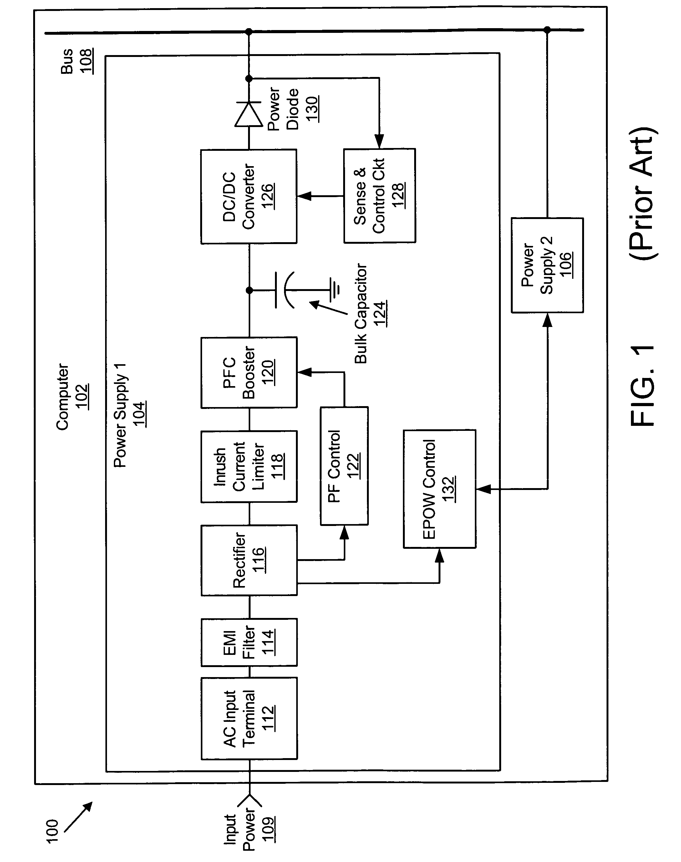
BACKGROUND OF THE INVENTION[0001]1. Field of the Invention[0002]This invention relates to holdup time provided by a power supply and more particularly relates to preserving energy in a power supply that has lost input power in order to maximize system holdup time.[0003]2. Description of the Related Art[0004]Computer systems use power supplies to convert power from one form to another. Other electronic systems use power supplies as well. Typically, a computer system requires that a power supply convert an alternating current (“AC”) input voltage to a direct current (“DC”) voltage that may be used for internal computer components. In other applications, a power supply converts an AC voltage to a DC voltage, and then back to an AC voltage.[0005]FIG. 1 is a schematic diagram 100 of a computer 102 with two AC-to-DC power supplies, power supply 1104 and power supply 2106, connected to a bus 108. The diagram 100 shows typical components of a power supply in power supply 1104. Typically, an...

Claims


Application Information

Patent Timeline
Patent Type & Authority Patents(United States)
IPC IPC(8): H02J7/00H02J9/00
CPCG06F1/30H02J9/061
Inventor JONES, CARL EVANKUBO, ROBERT AKIRALUCAS, GREGG STEVEN
Owner GOOGLE LLC
Why Eureka
Try Eureka