Touch screen panel with integral wiring traces

a touch screen panel and integral technology, applied in the field of integral wiring traces of touch screen panels, can solve the problems of inability to reliably connect solder joints, poor reliability of corner electrodes, and damage to electrodes of prior art devices, so as to achieve less labor intensive, less costly, and cost and time saving

Inactive Publication Date: 2008-01-22
3M INNOVATIVE PROPERTIES CO
View PDF28 Cites 11 Cited by
  • Summary
  • Abstract
  • Description
  • Claims
  • Application Information

AI Technical Summary

Benefits of technology

[0011]It is a further object of this invention to provide a touch screen panel with integral wiring traces which is more reliable than prior art touch screen panel assemblies.
[0012]It is a further object of this invention to provide a touch screen panel which has a more finished, neat, and low profile appearance.
[0014]It is a further object of this invention to provide such a method of manufacturing a touch screen panel with integral wiring traces which eliminates the possibility of damaging the corner electrodes of the touch screen panel and which eliminates the possibility of damaging the touch screen substrate.
[0015]It is a further object of this invention to provide such a method of manufacturing a touch screen panel with integral wiring traces which is less labor intensive and less costly than prior art methods.
[0017]It is a further object of this invention to provide a method of manufacturing such a touch screen panel in which the conductive silver paste of the edge electrode pattern and the wire trace pattern is co-fired with the protective coating thereby resulting in a cost and time savings.
[0018]This invention results from the realization that a more reliable, less labor intensive, less costly, and more aesthetically pleasing low profile touch screen panel assembly can be effected by integral wiring traces wherein the prior art individual wires are replaced with a wire trace pattern deposited on the resistive layer of the touch screen panel right on the panel either by printing or by some other method and then electrically isolating the wire trace pattern from the edge electrode pattern by laser etching or some other technique.

Problems solved by technology

The problem with such prior art devices are numerous.
The solder joints are often not very reliable and create solder humps on the smooth surface.
Moreover, the act of soldering the ends of each wire to the corner electrodes call damage the electrodes or even crack the substrate of the touch panel.
Also, this assembly process is labor intensive and hence costly.

Method used


Image

  • Touch screen panel with integral wiring traces
  • Touch screen panel with integral wiring traces
  • Touch screen panel with integral wiring traces

Examples


Embodiment Construction

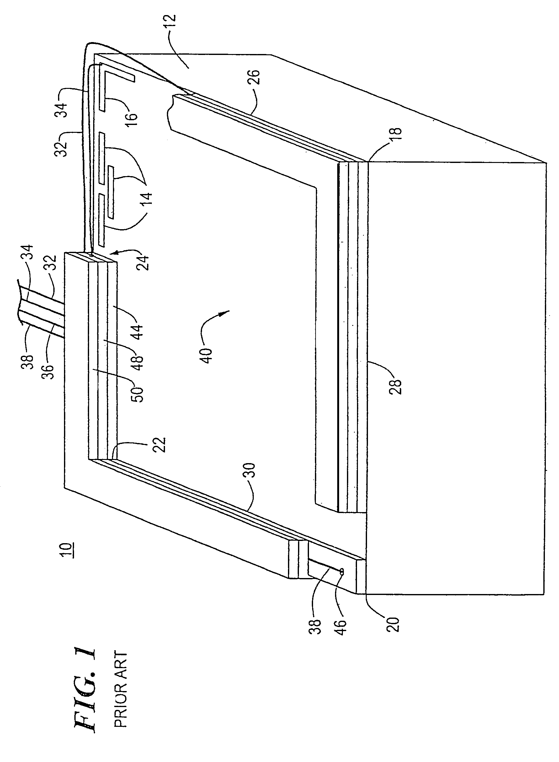
[0034]Prior art touch screen panel 10, FIG. 1, includes substrate 12 which usually includes an insulative layer (e.g., glass), a resistive layer over the primary working surface of the insulative layer, and a pattern of conductive edge electrodes 14 and terminal electrodes, usually corner electrodes 16, on the resistive layer as is knowing in the art. There are additional corner electrodes (not shown) one at each other corner 18, 20, and 22 of the touch screen. The edge electrodes 14 repeat in some predetermined patterned fashion along each edge 24, 26, 28, and 30 of panel 10.

[0035]Wires 32, 34, 36, and 38 extend to each corner electrode and with their ends stripped of insulation are soldered to the respective corner electrodes in order to generate the appropriate electrical field across the working surface 40 of panel 10. So, for example, wire 32 extends along edges 24 and 26 of panel 10 to the corner electrode (not shown) at corner 18; wire 34 extends along edge 24 of panel 10 to ...


PUM


Abstract

A method of manufacturing a touch panel wherein a glass substrate is coated with a resistive layer; a pattern of conductive edge electrodes and a conductive wire trace pattern are applied to the resistive layer; the conductive edge electrodes are electrically isolated from the conductive wire traces; and a protective insulative border layer is applied over the edge electrodes and the wire traces. A touch panel which includes a glass substrate coated with a resistive layer on one surface thereof; a pattern of edge electrodes on the resistive layer; a wire trace pattern on the resistive layer; a trench in the resistive layer between the wire trace pattern and the edge electrode pattern; and a protective insulative border layer over the edge electrode pattern and the wire traces.

Description

CROSS REFERENCE TO RELATED APPLICATIONS[0001]This application is a divisional of U.S. application Ser. No. 11 / 116,546, filed Apr. 27, 2005, now U.S. Pat. No. 7,102,624, which is a divisional of U.S. application Ser. No. 10 / 778,431, filed Feb. 16, 2004, now abandoned, which is a divisional of U.S. application Ser. No. 09 / 773,979, filed Feb. 1, 2001, issued as U.S. Pat. No. 6,727,895 on Apr. 27, 2004.FIELD OF THE INVENTION[0002]This invention relates to a touch screen panel with integral wiring traces which eliminates the bulky and unreliable prior art external wiring associated with touch screen panels and lowers the cost of manufacturing touch screen panel assemblies.BACKGROUND OF THE INVENTION[0003]Touch screen panels generally comprise an insulative (e.g., glass) substrate and a resistive layer disposed on the insulative substrate. A pattern of conductive edge electrodes are then formed on the edges of the resistive layer. The conductive electrodes form orthogonal electric fields ...

Claims


Application Information

Patent Timeline
Patent Type & Authority Patents(United States)
IPC IPC(8): G06F3/045
CPCG06F3/045
Inventor BOTTARI, FRANK J.MARBLE, ANDREA C.LACOURSE, MICHELE L.
Owner 3M INNOVATIVE PROPERTIES CO
Why Eureka
Try Eureka