
Device for laying and fixing pipes for various circuits, domestic or industrial

a technology for fixing devices and pipes, applied in the direction of vertical ducts, pipes, electrical equipment, etc., can solve the problems of unsatisfactory aesthetics and unsuitable laying of electrical conductor ducts, and achieve the effect of reducing laying time and cost and simplifying the pipe installation process

Inactive Publication Date: 2005-06-09
CACCIANI FABIEN +1
View PDF5 Cites 31 Cited by
  • Summary
  • Abstract
  • Description
  • Claims
  • Application Information

AI Technical Summary

Benefits of technology

[0006] Taking ducts for electrical conductors as a starting point, it is an object of the present invention to provide a fixing duct for pipes that simplifies the pipe installation process, and reduces laying time and costs while doing away with any finishing operation for pipes that remain visible.
[0010] By this means all the laying operations are effected faster than by the traditional method and the resulting installations are more finished and more aesthetically pleasing.
[0013] Each of these two provisions enables the pipe ducts or the finishing profile to be used for laying and retaining a variety of conductors. This is particularly beneficial when it comes to electrical or optical circuits which may be added well after the pipes have been installed, as it saves making chases in the walls, or using other contrivances to conceal these conductors in a habitable room where for example pipes have been laid along the baseboard or cornice and concealed by a finishing profile.

Problems solved by technology

In shape and structure, these ducts for electrical conductors are unsuitable for laying more rigid, heavier pipes of larger transverse dimensions than the conductors and in particular would be unable, by the force of the adhesive alone, to ensure permanent fixing of one or more pipes having a greater mass per unit length.
Furthermore, with visible pipes, these supports would form an aesthetically unpleasing system requiring complementary means to conceal them.

Method used


Image

  • Device for laying and fixing pipes for various circuits, domestic or industrial
  • Device for laying and fixing pipes for various circuits, domestic or industrial
  • Device for laying and fixing pipes for various circuits, domestic or industrial

Examples


Embodiment Construction

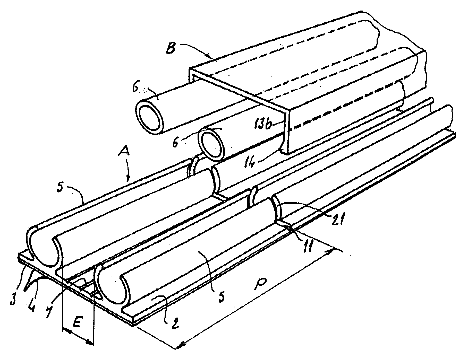
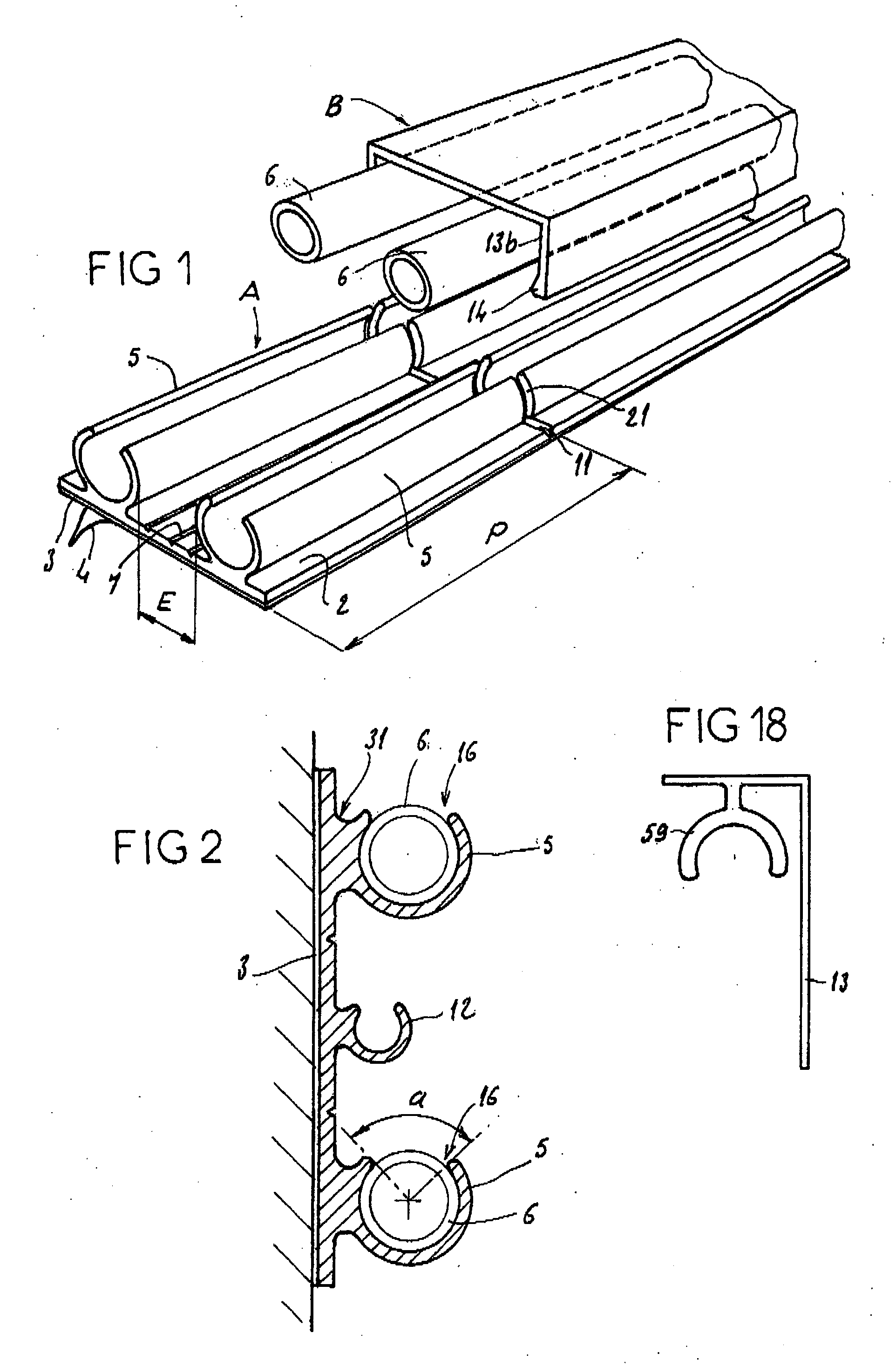
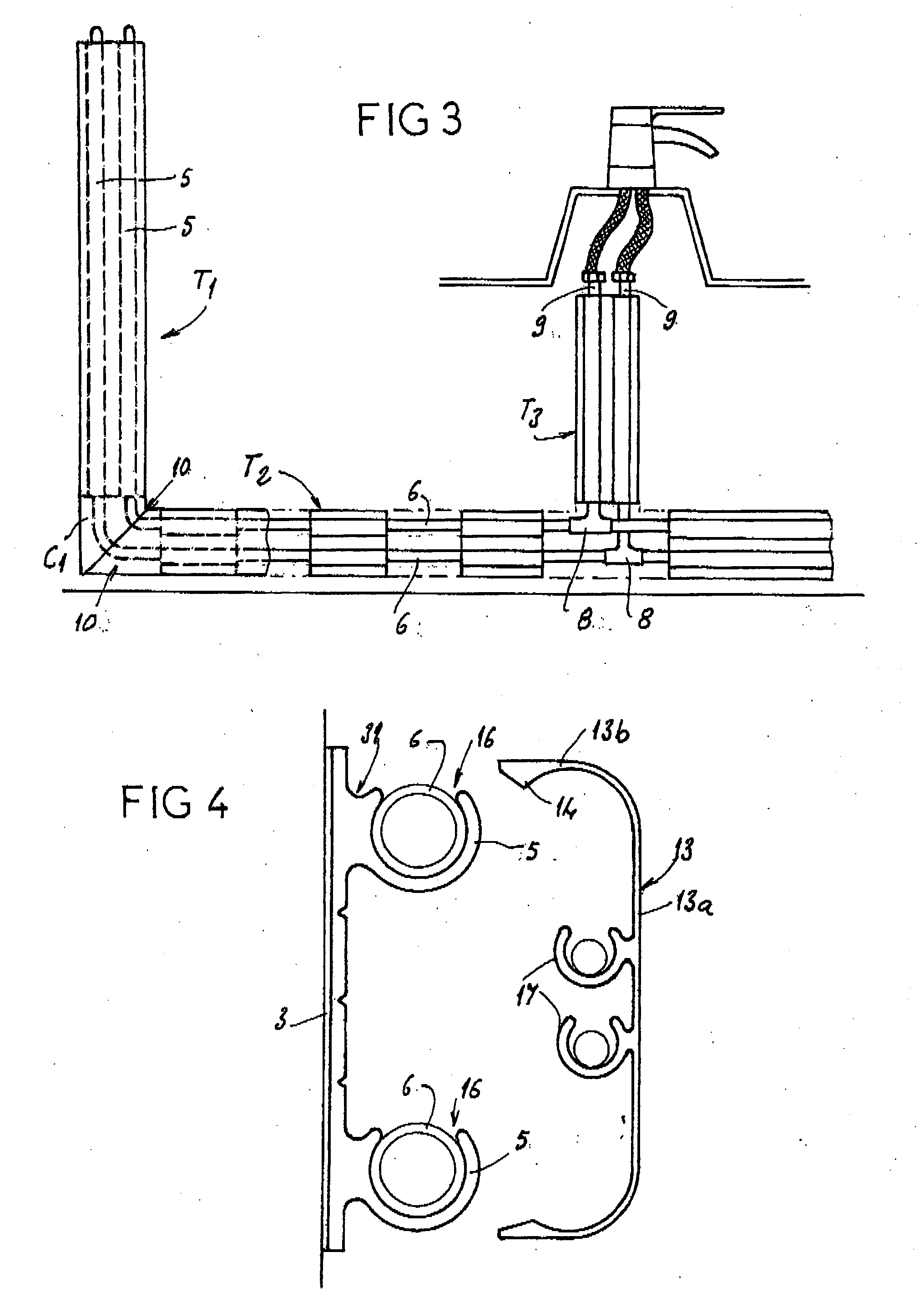
[0025] In FIG. 1, the reference A denotes a semirigid plastic profile comprising a mounting plate 2, on the back of which is a layer of adhesive 3 protected by a peel-off film 4. Projecting from the front of the mounting plate 2 are two open C-section gutters 5 whose internal dimension is appropriate for the pipes 6 with which these gutters are intended to engage. The two gutters are separated by a space E equal to or greater than the usual spacing of the pipes of the network in question.

[0026] In this space, the mounting plate 2 comprises one or more breakable longitudinal lines 7 consisting of a reduction in the thickness of its component material, and / or consisting of precuts (not shown). It also comprises breakable transverse lines 11 that are also formed by a thinning of the material or by a precut, and coincide with slots 21 running through the gutters 5 all the way to the mounting plate 2. In practice the spacing P from each breakable line and slit 21 to the next is about 10...


PUM


Abstract

The invention concerns a device comprising a profiled section A made of plastic material with a base plate (2) whereof the reverse side is equipped with means for adhesive fixing (3) against a wall and the face is provided with elastically deformable wings defining in pairs longitudinal troughs (5) with C-shaped cross-section, arranged projecting and transversely spaced apart from one another, at least one of the wings of each trough being integral with the base plate and made of the same semirigid material. The base plate (2) is divided into sections by cleavable or precut transverse lines, coincident with transverse grooves (21) provided in the trough (5), to form in the profiled section independent laying supports. A finish profiled section made of plastic material B provided with snap-on fixing means on the trough (5), is longitudinally cleavable to cover one or several laying supports and the associated pipes (6).

Description

BACKGROUND OF THE INVENTION [0001] The invention relates to a laying and fixing system for pipes of various circuits, domestic or industrial. [0002] It therefore relates to pipes for heating, hot and cold water supply, and all other fluid circuits as well as pipes for the protection of electrical circuits or signal-transmission circuits. During the construction of a network of pipes, it is necessary to preform each pipe on site and preposition it before fixing it in place definitively. These operations then have to be repeated for each pipe or conduit. [0003] This preparation is time-consuming for the metal or plastic pipes which are bent on demand, but also pipes made up of straight lengths connected by T or C fittings attached by welding, brazing or adhesive bonding. DESCRIPTION OF THE PRIOR ART [0004] Documents FR 1 319 291, FR 2 568 730 and BE 571 724 disclose moldings or ducts formed from a continuous profile comprising a fixing mounting plate with a flat back covered by an adh...

Claims


Application Information

Patent Timeline
IPC IPC(8): F16L3/13F16L3/22F16L3/223F16L3/237F16L3/26H02G3/04
CPCF16L3/13F16L3/223H02G3/0431F16L3/26F16L3/237
Inventor CACCIANI, FABIENHOFFMANN
Owner CACCIANI FABIEN
Learn More