Floor located vehicle container holder

a vehicle and container technology, applied in the field of vehicle container holders, can solve the problems of limiting the access to storage, spilling liquid, and much to be desired, and achieve the effects of reducing manufacturing costs, reducing the center of gravity of the container within the vehicle, and reducing the range of adjustment/varian

Inactive Publication Date: 2005-09-15
ANDREWS MICHAEL L
View PDF37 Cites 10 Cited by
  • Summary
  • Abstract
  • Description
  • Claims
  • Application Information

AI Technical Summary

Benefits of technology

[0010] The mounting portion of the container holder slips behind a vehicle component adjacent a vehicle floor. The container holder need not be permanently affixed to any interior surface of the vehicle. The container holder rests on or just above the vehicle floor, such that the contents rest on the floor of the vehicle. Notably, the container holder does not include a bottom and utilizes the vehicle floor or other vehicle component as the bottom rest for the retained container. Such a bottomless design provides greater ability to handle a range of container sizes and provides a greater range of adjustment / variance with respect to differing vehicles, lowers the container center of gravity within the vehicle, and reduces manufacturing expense.
[0011] Another container holder embodiment of the present invention includes a mounting section with a multiple of mounting pins which extend from a pin plate mounted to a rear container portion of the container holder generally opposite the arm ends. The mounting pins maintain the container holder in place, but are light enough to flex and release in the event some unusual force is applied (e.g., a seat is moved forward quickly, someone pulls hard, etc.) The container holder requires only a carpeted panel to receive the pins. Benefits include a somewhat easier installation, a more finished and interior-neutral appearance, more flexibility as far as placement, and better adaptability across cars (including greater potential for transferring it to other / future cars.)
[0012] If, by chance, a spill does happen (most likely due to the container itself and not the holder), the spill will be upon the vehicle floor and mats which are relatively easily cleaned. Moreover, the spill will not affect the vehicle electronic system, switches, gear shifters, or other difficult to clean areas and components and there is less potential for launching the container within the vehicle in the event of rapid maneuvers due to the low mounting location within the vehicle.
[0013] The present invention therefore provides a vehicle container holder which is readily adapted and securely mounted within a multiple of different vehicles, minimizes spillage, is more safe, avoids interfering with vehicle controls yet is presented in a convenient location, does not utilize existing storage space, and is relatively inexpensive.

Problems solved by technology

Conventional cup holders often may leave much to be desired.
The cup holders may often be located in an inconvenient position that is not readily accessible or which interferes with vehicle controls or instruments.
Other cup holder locations may share space with other vehicle storage thereby limiting access to that storage.
Still other cup holders are often positioned relatively high within the vehicle in a manner in which a quick stop or rapid maneuver may result in spilled liquid.
Moreover, spillage or condensation from center console mounted cup holders may fall upon vehicle electronic system, switches, gear shifters, or other difficult to clean areas and components.
Numerous after-market cup holders have been developed with varying degrees of effectiveness but often suffer from the previously mentioned deficiencies.
Such deficiencies may be further magnified due to an aftermarket cup holder's lack of a readily adaptable and secure mounting structure.

Method used


Image

  • Floor located vehicle container holder
  • Floor located vehicle container holder
  • Floor located vehicle container holder

Examples


Embodiment Construction

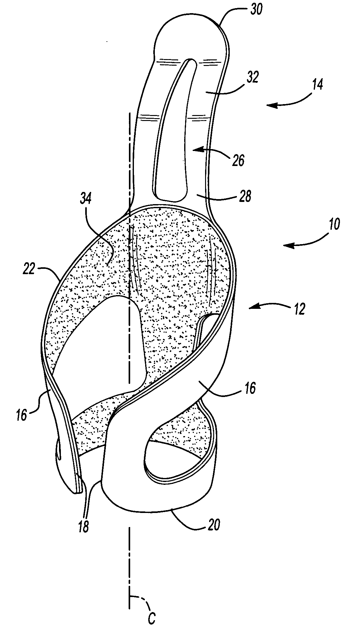
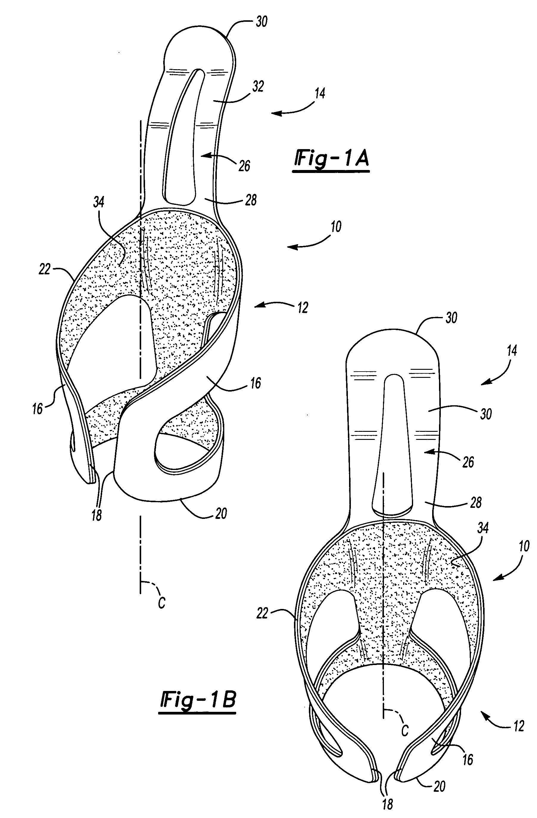
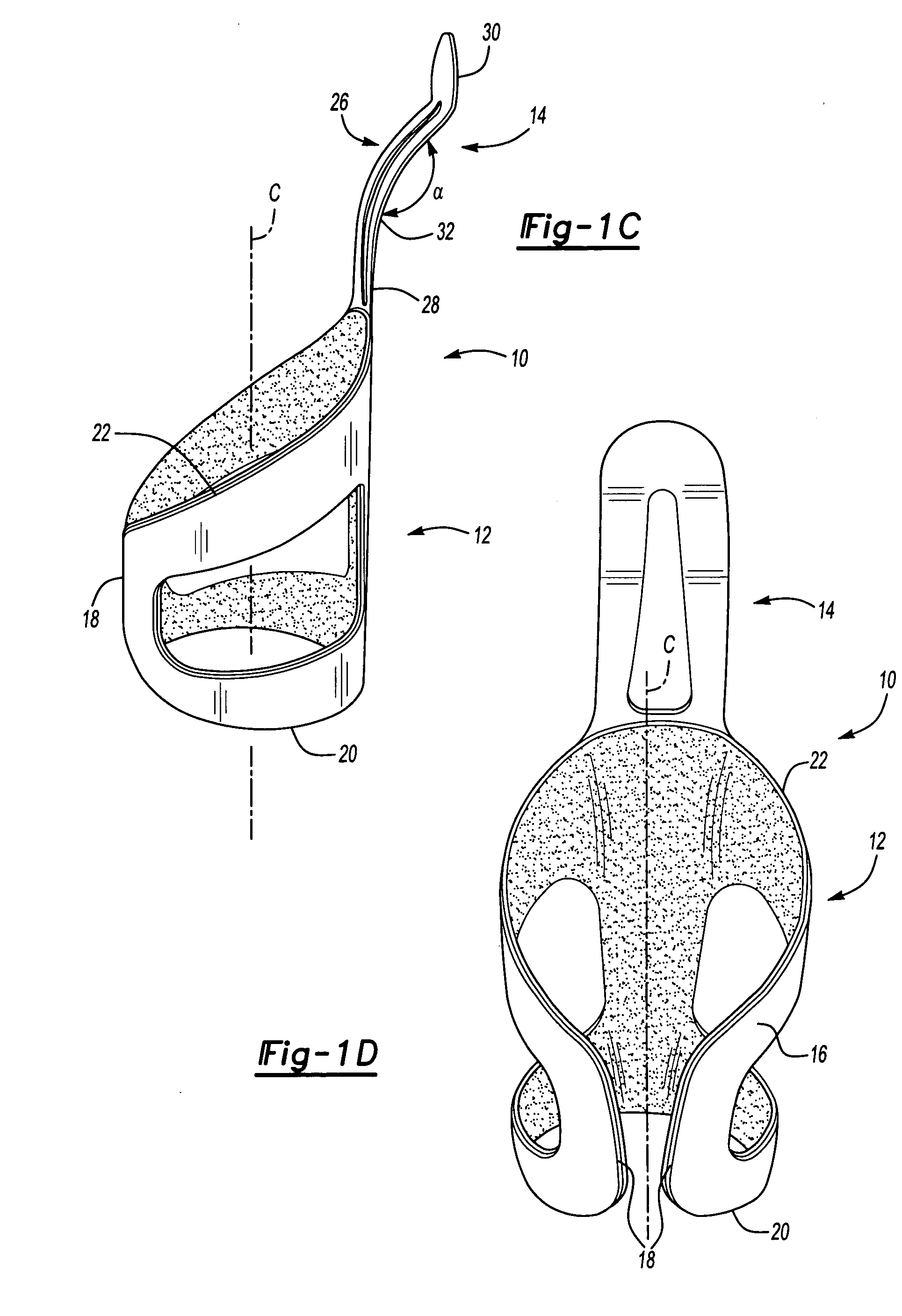
[0036]FIGS. 1A-1E illustrate a general perspective view of a vehicle container holder 10 designed according to the present invention. The container holder 10 generally includes a bottomless container retention section 12 and a mounting section 14.

[0037] The container retention section 12 defines a container axis C along which a container is received (FIG. 3). The container retention section 12 includes arms 16 which at least partially surround the container axis C. Two arms 16 having arm ends 18, which do not meet, are preferred such that a cup handle H (FIG. 4) may be received therebetween; however, a single continuous arm is contemplated by the present invention.

[0038] The arms 16 are generally arcuate. The arms 16 are preferably of a frustro conical geometry (FIG. 1B) in which a lower portion 20 of the arms 16 defines a smaller perimeter than the upper portion 22 of arms 16. It should be understood that relative positional terms such as “forward,”“aft,”“upper,”“lower,”“above,”“...


PUM


Abstract

A vehicle container holder includes a bottomless container retention section and a mounting section. The container retention section defines a container axis along which a container is received and rested upon the vehicle interior component. The mounting portion of the container holder slips behind a vehicle component adjacent a vehicle floor or includes a multiple of pins to penetrate into a carpeted panel along the vehicle transmission tunnel. The container holder utilizes the vehicle floor as the bottom support for the retained container. Such a bottomless design provides greater ability to handle a range of container sizes and provides a greater range of adjustment/variance with respect to vehicle designs while simplifying manufacturing.

Description

[0001] The present application is a Continuation in Part of U.S. patent application Ser. No. 10 / 427,775, filed May 1, 2003.BACKGROUND OF THE INVENTION [0002] The present invention relates to a vehicle container holder and, more particularly, to a vehicle container holder which utilizes the vehicle floor as a container support surface. [0003] Beverage holders are common within current foreign and domestic vehicles. Many differing types of such beverage holders commonly referred to as cup holders exist and are located at various positions within the vehicle. Oftentimes, the cup holders are movable between a stowed and an extended position to minimize obstructing driver or passenger movement within the vehicle when in use. [0004] Conventional cup holders often may leave much to be desired. The cup holders may often be located in an inconvenient position that is not readily accessible or which interferes with vehicle controls or instruments. Other cup holder locations may share space wi...

Claims


Application Information

Patent Timeline
Patent Type & Authority Applications(United States)
IPC IPC(8): B60N3/10
CPCB60N3/108B60N3/103
Inventor ANDREWS, MICHAEL L.
Owner ANDREWS MICHAEL L
Why Eureka
Try Eureka