Adjustable load stabilizer method and apparatus

a technology of load stabilizer and adjustable bar, which is applied in the direction of load securing, load accommodation, transportation items, etc., can solve the problems of affecting the stability of the rail car

Active Publication Date: 2008-01-29
MBULL HLDG LLC
View PDF17 Cites 15 Cited by
  • Summary
  • Abstract
  • Description
  • Claims
  • Application Information

AI Technical Summary

Benefits of technology

[0014]It is a general object of the subject invention to provide a novel method and apparatus to stabilize cargo within a ship hold, transport container, box car, truck trailer, and the like which will obviate or minimize problems and concomitantly achieve at least some of the desired aspects of cargo stabilization of the type previously described.
[0015]It is another general object of the subject invention to judiciously protect cargo from damage during transport and to provide enhanced stabilization of cargo within a ship hold, transport container, box car, truck trailer, and the like by minimizing shifting of cargo during transport.
[0016]It is a specific object of the invention to provide a stabilization method and apparatus for a transport container, and the like, with enhanced strength to stabilize cargo against transport forces such as swaying, lateral shifting and other forms of shifting of cargo within a ship hold, transport container, box car, truck trailer, and the like.

Problems solved by technology

Although each individual component of cargo may be quite heavy and stationary at rest, the mass of a transport load can produce considerable momentum force as a ship, railroad car, truck trailer or truck body is placed in motion, stops, or changes direction.
When a railroad car is rolled into a stationary string of cars, the impact causes the car couplings to lock together with a jolt.
This impact can apply a significant force to cargo within the rail car.
Moreover, during transport, railroad cars and overland transport vehicles are subject to braking forces, bumps, centrifugal forces on curves, vibration, dips in the track or road, swaying, run-in or run-out forces, etc.
Such forces can result in damage to the cargo, damage to the interior walls or doors of the container, damage to the cargo packaging, and may even create dangerous leaks if the cargo is a hazardous material.
Accordingly, it is undesirable to permit cargo to gain any momentum independent of other cargo or a transport container.
Each of these previously known systems has limitations associated with cost, lack of strength, amount of labor required for installation, time expended for installation, lack of flexibility and securement integrity.
These systems while useful for known rectangular voids can exhibit impaired performance due to size and / or dimension variance.
Moreover curved surfaces can not be accommodated well with rectangular shaped void fillers.
The difficulty in applying various rectangular units to irregular shapes and the on site adjustment for varying sizes of voids to be filled, the unsuitability of corrugated board to absorb strong compression forces, and the use of materials not fully resistant to moisture can impair use of this type of dunnage void filler system.
Other known means of restraint such as the use of inflatable dunnage bags used alone or in combination with collapsible void fillers have tended to exhibit the disadvantage that air bags are subject to rupturing, leakage and loss of air pressure, or simply contraction and securement loosening in low temperature environments.
In addition to the above, other restraining systems known in the past often required additional elements and equipment which tended to be cumbersome to store, arduous to handle and / or install, and often required a degree of skilled labor in application.
Finally, in certain instances wood block and bracing has been used in the past to fill voids and secure loads; however, wood bracing is somewhat time consuming to install and often requires skilled or semi-skilled labor which is often contracted out to third parties.
In addition certain wood materials are not suitable for international transport without fumigation which increases the overall cost of the securement system.
The problems suggested in the preceding are not intended to be exhaustive but rather are among many which may tend to reduce the effectiveness of load stabilizer methods and apparatus appearing in the past.

Method used


Image

  • Adjustable load stabilizer method and apparatus
  • Adjustable load stabilizer method and apparatus
  • Adjustable load stabilizer method and apparatus

Examples


Embodiment Construction

Context of the Invention

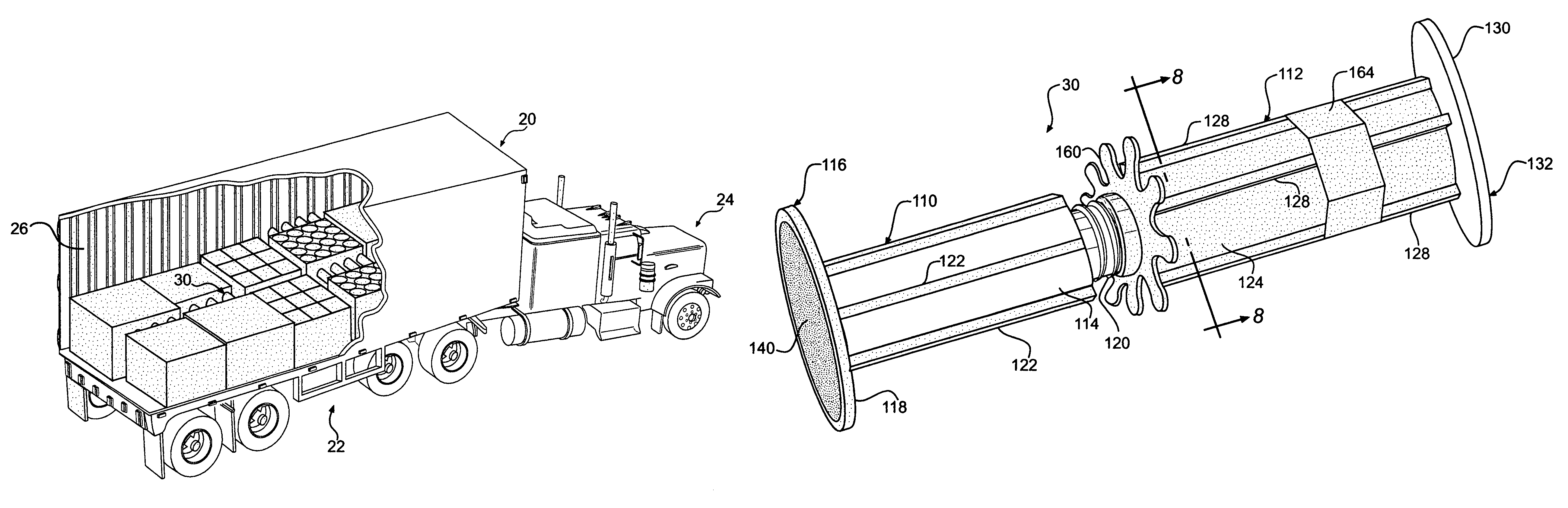
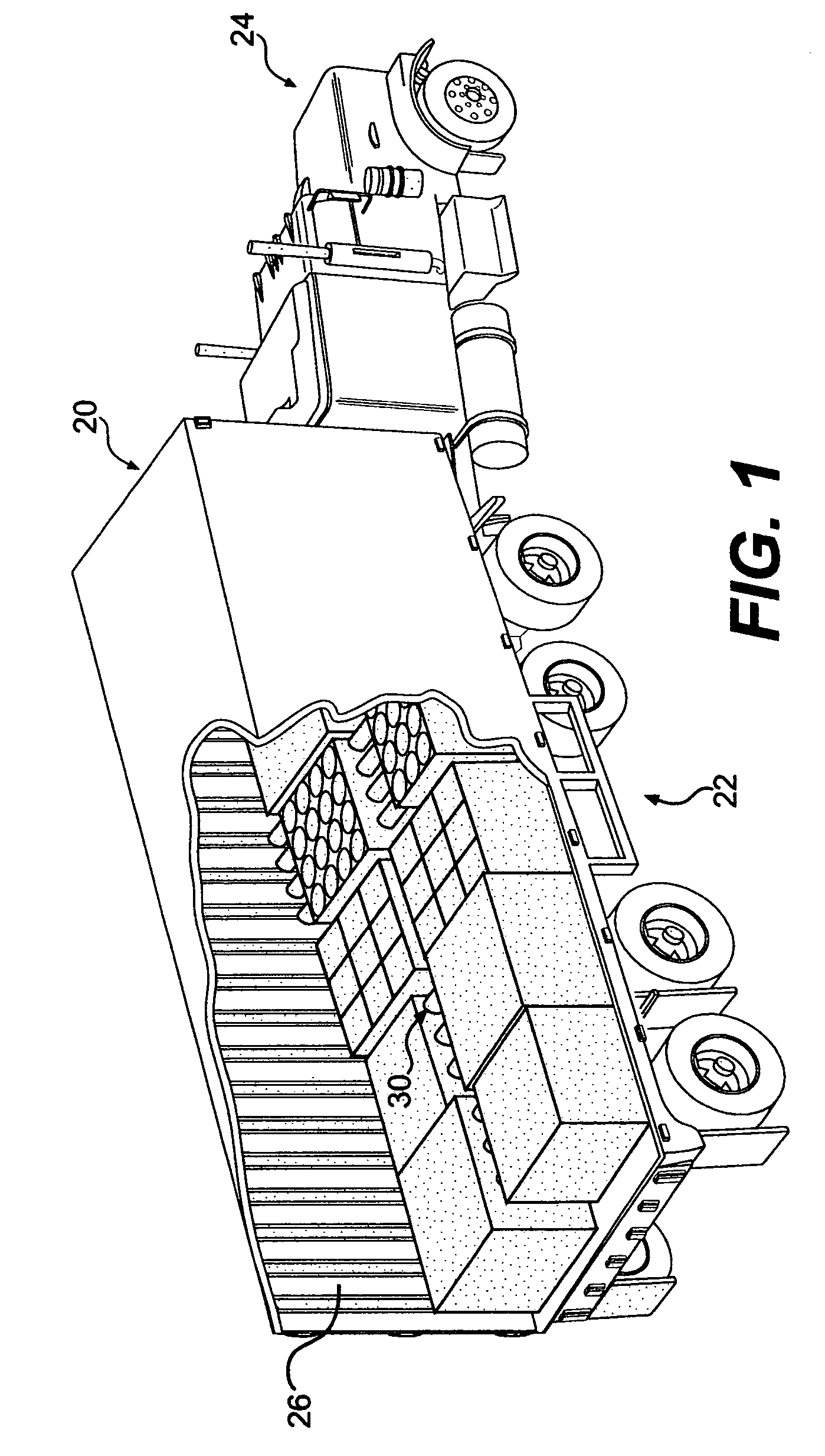
[0035]Turning now to the drawing wherein like numerals indicate like parts, FIG. 1 shows an axonometric view of an operating environment of the invention. In this, a transport or cargo container 20 is shown mounted upon a trailer 22 which is towed by a tractor 24 for land transport. Containers such as these are also operable to be mounted on railway flat cars either directly or attached to trailers 22. This form of container is merely illustrative and the subject invention can be used to advantage in ship cargo holds, intermodal containers, tractor trailers, overland truck bodies, rail road boxcars, and the like.

[0036]A partially cut away portion of FIG. 1 depicts various size and shapes of cargo, which are stabilized against each other and against the internal walls 26 of the container 20 by load stabilizers 30 in accordance with the subject invention.

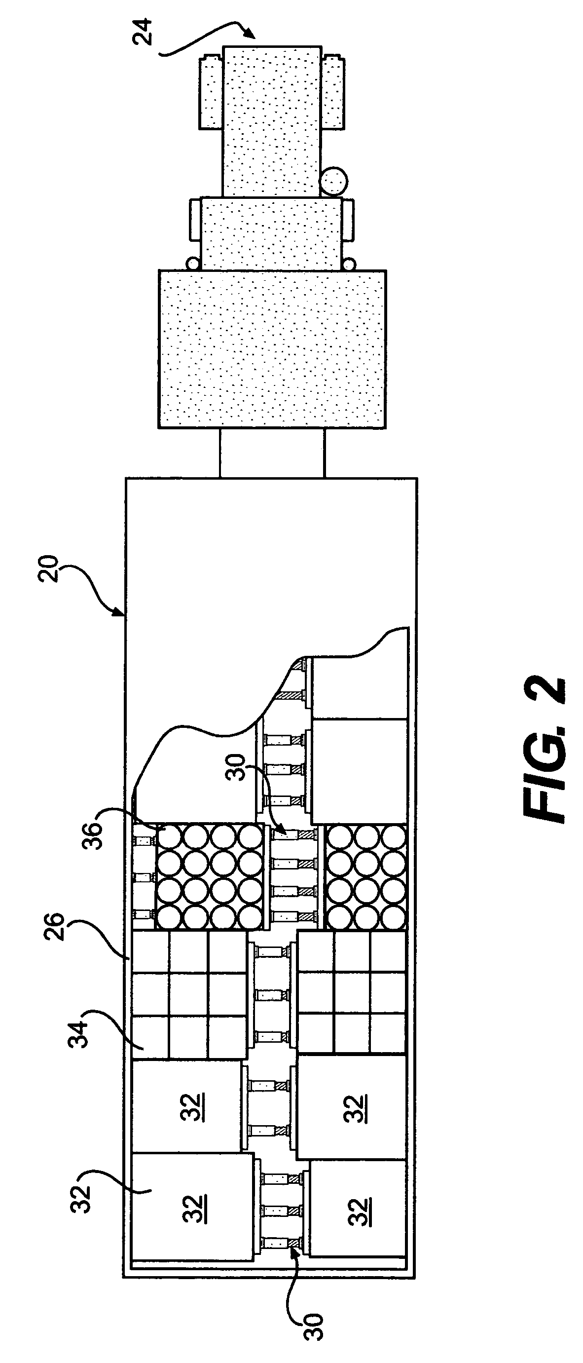
[0037]FIG. 2 further illustrates details of the illustrative operating environment shown in FIG. 1. In this ...


PUM


Abstract

The present invention is directed to an apparatus and method for stabilizing cargo within a transport container. An apparatus includes first and second tubular elements having generally cylindrical bodies and bases at one end which can react against opposing surfaces within the transport container and stabilize cargo within the container. One base of one tubular member can react against a surface of cargo and the other base of the other tubular member can react against an opposing surface of other cargo or an internal wall of the transport container. An extension mechanism allows for the extension and selective translation between the first and second tubular members allowing the apparatus to extend and fill the space between opposing surfaces within the transport container and stabilize the cargo. A method for stabilizing cargo within a transport container includes providing an extensible load stabilizer having first and second tubular elements, each having a base, positioning the load stabilizer between opposing surfaces within the transport container, and extending the tubular members with respect to each other, and stabilizing a surface of cargo against an opposing surface.

Description

RELATED PATENTS[0001]This application relates to U.S. Pat. No. 6,089,802 entitled “Cargo Restraint System for a Transport Container” issued on Jul. 18, 2000, U.S. Pat. No. 6,227,779 entitled “Cargo Restraint Method for a Transport Container” issued on May 8, 2001, and U.S. Pat. No. 6,607,337 entitled “Cargo Restraint System” issued on Aug. 19, 2003, all of common inventorship and assignment as the subject application.BACKGROUND OF THE INVENTION[0002]This invention relates to an improved method and apparatus for stabilizing cargo during transportation. More particularly, this invention relates to a novel method and apparatus for stabilizing and restraining undesired movement of drums, boxes, rigid and flexible containers, palletized or not palletized, within the interior of a transport container or the like with respect to each other and / or with respect to the internal walls of the container.[0003]Most shipments for transport are placed in enclosures such as ship cargo holds, intermo...

Claims


Application Information

Patent Timeline
Patent Type & Authority Patents(United States)
IPC IPC(8): B60P7/08
CPCB60P7/08B60P7/135
Inventor BULLOCK, MATTHEW
Owner MBULL HLDG LLC
Why Eureka
Try Eureka