Turbine unit and VTG mechanism therefor

a turbine unit and vtg technology, applied in the direction of positive displacement liquid engine, piston pump, liquid fuel engine, etc., can solve the problems of increased fabrication cost, unfavorable practical application, and inability to reasonably manufacture, etc., to achieve simple and easy-to-assemble construction

Active Publication Date: 2008-01-29
BORGWARNER INC
View PDF16 Cites 38 Cited by
  • Summary
  • Abstract
  • Description
  • Claims
  • Application Information

AI Technical Summary

Benefits of technology

[0005]The invention has the objective to create a simple and easy to assemble construction of a VTG mechanism while using (at least) one roller bearing that maintains said advantages.

Problems solved by technology

Although this document is older than twenty years already, it has had no impact on any practical application.
The reason is probably that the turbine housing—in order to house the roller bearing—has such a complicated shape that it could not be reasonably fabricated.
In addition the necessary surface treatments on portions which are not easily accessible, would have additionally increased fabrication cost.
The measures which are taken in order to allow access to parts which possibly need repair, weaken the housing, and result in an unacceptable lack of operational security.
This disclosure—in spite of the likely advantages of a roller bearing—was not sufficiently matured and therefore not suitable for practical application.

Method used


Image

  • Turbine unit and VTG mechanism therefor
  • Turbine unit and VTG mechanism therefor
  • Turbine unit and VTG mechanism therefor

Examples


Embodiment Construction

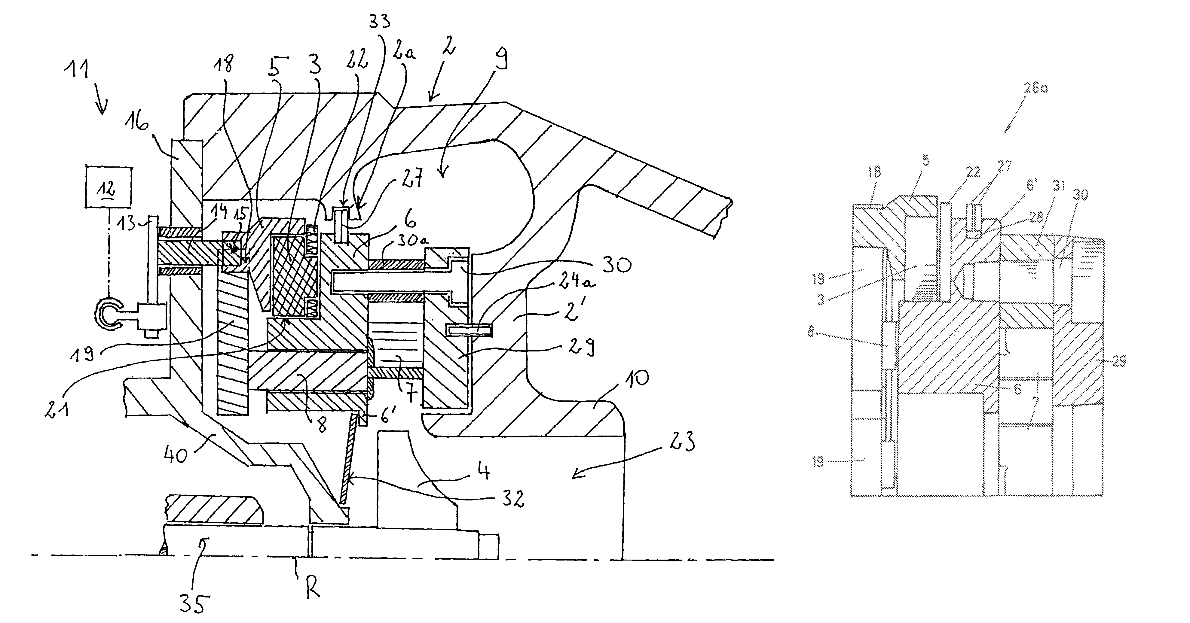
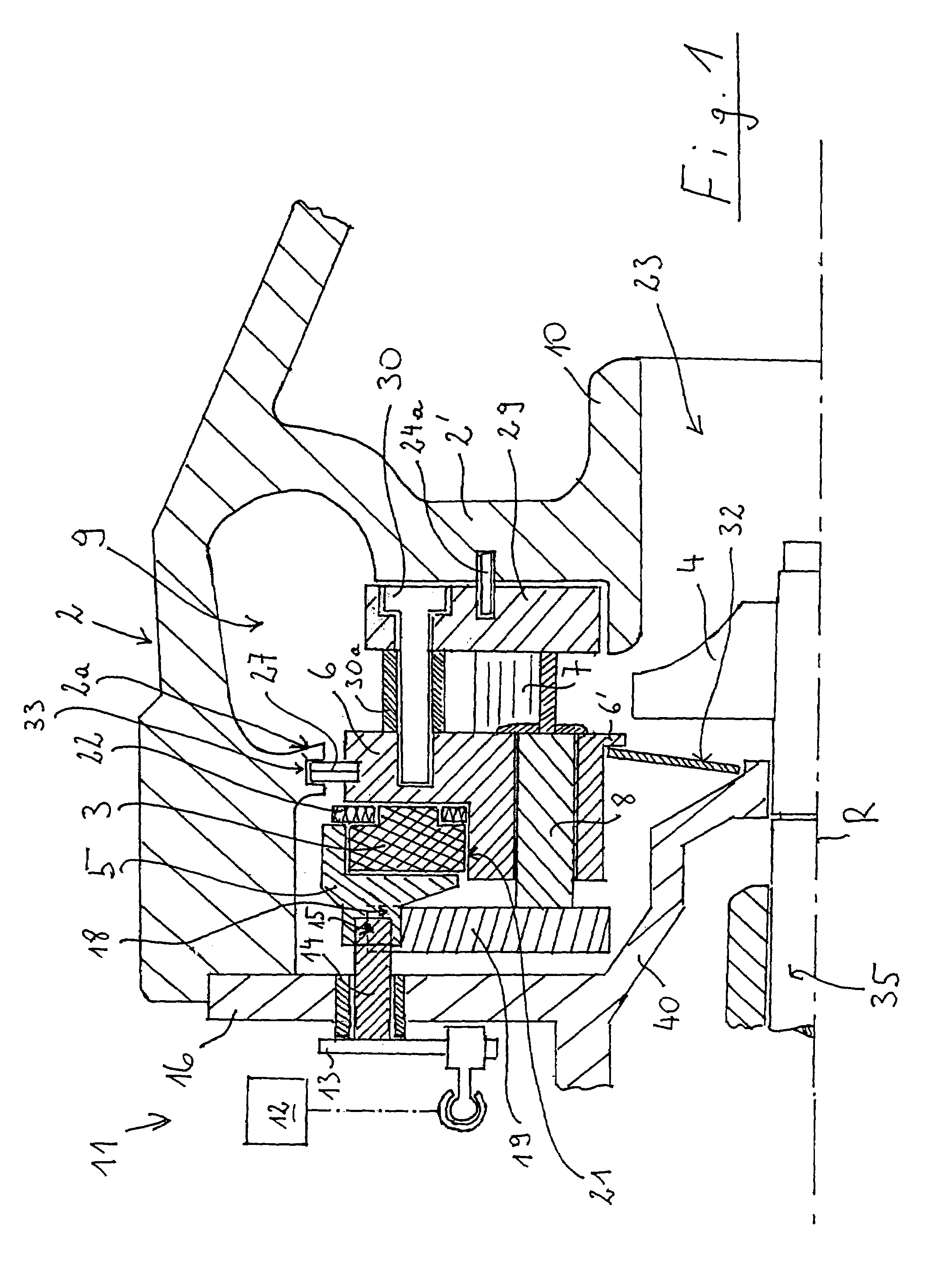
[0025]According to FIG. 1 a turbine housing 2 is connected with a flange 16 of the bearing housing, from which a cylindrical member 40 extends into the turbine housing 2 and carries shaft 35 of a turbine rotor 4. The turbine housing 2 comprises an admission channel 9 which surrounds a turbine rotor 4, guiding a fluid which drives turbine rotor 4 (in the case of a turbocharger this fluid is an exhaust gas of a combustion engine), a rotor space 23 and an axial cylinder 10 through which the fluid, respectively the exhaust gas, will be discharged.

[0026]In order to lead fluid to turbine rotor 4 in regulated or controlled manner, a device is provided at the exit of an admission channel 9 before rotor space 23, which is known in the art as VTG (variable turbine geometry) mechanism. This VTG mechanism comprises in principle a crown of movable vanes 7 concentrically surrounding turbine rotor 4 (see FIG. 4), which are carried by control shafts 8 which are firmly connected thereto, and which a...


PUM


Abstract

A turbine unit having a rotor housing (2) having at least one admission channel (9) for a fluid, as well as a turbine rotor (4) which is supported in a turbine space (23) of the rotor housing (2) and wherein fluid is led into the turbine space (23) at its periphery through a VTG mechanism (5-8) of variable turbine geometry. The VTG mechanism (5-8) has a nozzle ring (6) having a plurality of vane shafts (8) which are arranged in the form of a crown on the nozzle ring (6) and which carry on one of their ends vanes (7) which can be moved from a substantially tangential position (relative to the crown) into a substantially radial position, as well as at least one control element (19) in order to pivot the orientation of the vanes (7).

Description

CROSS REFERENCE TO RELATED APPLICATION[0001]This application is based upon European Patent Application No. 02 018 295.2, filed Aug. 26, 2002, from which priority is claimed.TECHNICAL FIELD[0002]The present invention relates to a turbine unit—in particular, a turbocharger, as well as for other types of fluid flow machines, such as secondary air pumps—comprising a turbine rotor housing having at least one admission channel for a fluid—in the case of an employment of the invention for a turbocharger this will be the exhaust gas of a combustion engine—and a turbine rotor, which is housed in a turbine space of the rotor housing and said fluid is led to the periphery of the turbine rotor through a variable geometry mechanism. The variable geometry mechanism comprises a nozzle ring having a plurality of nozzle shafts which are arranged in the nozzle ring in the form of a crown, and wherein each shaft has nozzle vanes fixed to one of its ends, said nozzle vanes being capable of being adjust...

Claims


Application Information

Patent Timeline
Patent Type & Authority Patents(United States)
IPC IPC(8): F01D17/16F01D25/24F02D23/00F04D1/10F04D29/44F04D29/56F02B37/24F16C19/06F16C19/22F16C25/08F16C33/58F16C33/78F16C35/06F16C43/04
CPCF01D17/165F05D2230/642F05D2230/61
Inventor STILGENBAUER, MICHAEL
Owner BORGWARNER INC
Why Eureka
Try Eureka