Maxillary distraction device

a distraction device and maxillary bone technology, applied in the field of maxillary bone extension devices, can solve the problems of deformation, deformation, difficulty in chewing or breathing, and deformation of the maxillary bone, and achieve the effect of lengthening the maxillary bon

Inactive Publication Date: 2008-01-29
OSTEOMED
View PDF23 Cites 17 Cited by
  • Summary
  • Abstract
  • Description
  • Claims
  • Application Information

AI Technical Summary

Benefits of technology

[0012]In accordance with a further aspect of the invention, a method of performing osteogenesis of the maxillary bones includes the steps of implanting anchors in the right and left side maxillary bones, connecting a facebow to the anchors wherein the facebow extends entirely within the mouth across a midline of the patient, and lengthening the facebow periodically to lengthen the maxillary bones. Preferably, the facebow lengthens the maxillary bones and teeth in all three planes of space simultaneously.

Problems solved by technology

Such a condition may lead to difficulties in a patient's movement.
A small jaw can cause difficulties in chewing or breathing (obstructive sleep apnea).
Moreover, deformations. are often psychologically distressing to the patient, especially when the deformations occur in craniofacial bones.
Such devices have the shortcoming that they can not easily be adjusted once set.
While these devices may achieve the desired end result of lengthening the deformed bone, they are unwieldy. and unsightly, thereby preventing the user from engaging in many activities during the lengthening procedure.
They also create unsightly scars where the pins extend through the skin.
This scarring is particularly undesirable when they are located on the face.
However, the implantable devices do not connect the right and left sides of the skull together to achieve better stability and simultaneous distraction with a single device.

Method used


Image

  • Maxillary distraction device
  • Maxillary distraction device
  • Maxillary distraction device

Examples


Embodiment Construction

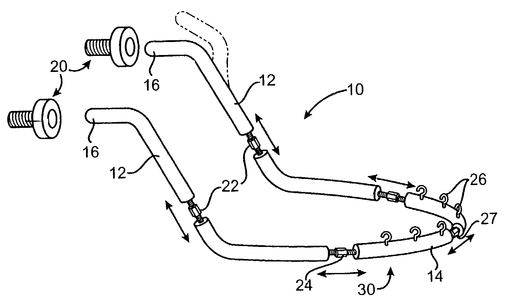
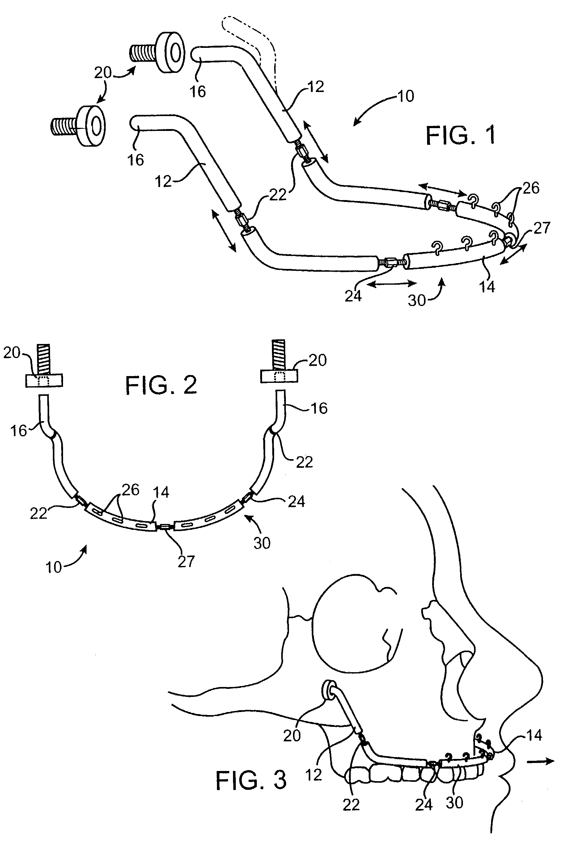
[0023]FIGS. 1-3 illustrate a first embodiment of a maxillary distraction device 10 for providing anterior traction on the maxilla and midface. Distraction devices, such as those shown and described herein are generally used to lengthen bones to correct abnormalities and after facial fractures and injuries. The distraction device 10 of FIG. 1 includes two anchors 20 and a facebow 30. The facebow 30 includes two generally vertical posterior legs 12 connected to opposite ends of a substantially horizontal U-shaped anterior portion 14. The posterior legs 12 each have a free end 16 which is removably connectable to the implantable anchors 20. The implantable anchors 20 are in the form of large bone screws or other implants configured to be implanted into the maxillary bones at the malar region of the skull with the free ends or heads of the screws positioned within the mouth.

[0024]The implantable anchors 20 provide a fixation of the posterior ends of the facebow 30 to the skull while the...


PUM


Abstract

A device for maxillary jawbone and dentition expansion and / or retraction is configured for mounting within the mouth and connects the right and left halves of the skull. The maxillary distraction device includes at least two implantable anchors configured to be implanted in the maxillary bones of the skull on opposite sides of a midline of the skull. A facebow having two posterior ends is connectable to the implantable anchors and is configured to extend from the maxillary regions entirely within the mouth across the midline of the skull. The facebow has at least one expandable section for bone lengthening. The facebow is connected to the anchors and is lengthen periodically to lengthen the maxillary bones. The facebow may provide horizontal, vertical, and transverse distraction.

Description

RELATED APPLICATIONS[0001]This application is a continuation of U.S. patent application Ser. No. 09 / 988,529 filed Nov. 20, 2001 by Applicants and entitled “Maxillary Distraction Device,” now U.S. Pat. No. 6,589,250.TECHNICAL FIELD OF THE INVENTION[0002]The invention relates to a device and method for jaw bone expansion, and more particularly, the invention relates to a device and method for creating traction on the upper jaw and dentition.DESCRIPTION OF THE RELATED ART[0003]Bones sometimes develop at different rates, leaving some bones disproportionately shorter than other bones. Alternatively, injury may leave a bone shorter than its original length. Such a condition may lead to difficulties in a patient's movement. For instance, a patient with a shortened tibia may need special shoes for assistance in walking. A small jaw can cause difficulties in chewing or breathing (obstructive sleep apnea). Moreover, deformations. are often psychologically distressing to the patient, especiall...

Claims


Application Information

Patent Timeline
Patent Type & Authority Patents(United States)
IPC IPC(8): A61B17/58A61B17/60A61B17/66
CPCA61B17/663
Inventor SCHENDEL, STEPHEN A.
Owner OSTEOMED
Why Eureka
Try Eureka