Cyclone separator

a technology of cyclone separator and separator plate, which is applied in the direction of maintenance and safety accessories, liquid separation agent use, dispersed particle filtration, etc., can solve problems such as improper functions

Inactive Publication Date: 2008-01-29
HILTI AG
View PDF9 Cites 51 Cited by
  • Summary
  • Abstract
  • Description
  • Claims
  • Application Information

AI Technical Summary

Benefits of technology

[0008]This and other objects of the present invention, which will become apparent hereinafter, are achieved by providing a particle outlet having at least two particle outlet openings, with the dirty air inlet opening into the vortex chamber between the at least two particle outlet openings. As a result of provision of the at least two openings the abrasion particles can move in more that one direction under the action of the gravity force from the vortex chamber. In this way, a satisfactory separation effect is insured for all of the possible directions of orientation of the cyclone separator relative to the gravity force.
[0010]In this way, the particle outlet openings are provided on opposite, with respect to the mouth of the dirty air inlet, sides of the vortex chamber. This insures that at least one of the particle outlet openings would lie at least at the same height as the mouth of the dirty air inlet. The cylindrical shape of the vortex chamber permits to form a stable vortex that insures that almost all of the abrasion particles, which are heavier than air, can closely move along the inner wall of the vortex chamber.
[0012]Advantageously, the two immersion pipes are connected with a common pure air outlet opening of the pure air outlet. Thereby, it is possible to provide for a necessary suction stream from the dirty air inlet up to the pure air outlet with a single suction ventilator arranged downstream of the cyclone separator. The advantage of this construction consists in that the pure air passes past the suction ventilator, reducing the danger of the ventilator being damaged and reducing its possible wear.
[0013]Advantageously, at least one filter is provided between the immersion pipes and the pure air outlet, whereby the cleaning effect can be increased.

Problems solved by technology

A drawback of the known cyclone separator consists in that it properly functions only when it is oriented in a predetermined direction in space.

Method used


Image

  • Cyclone separator
  • Cyclone separator
  • Cyclone separator

Examples


Embodiment Construction

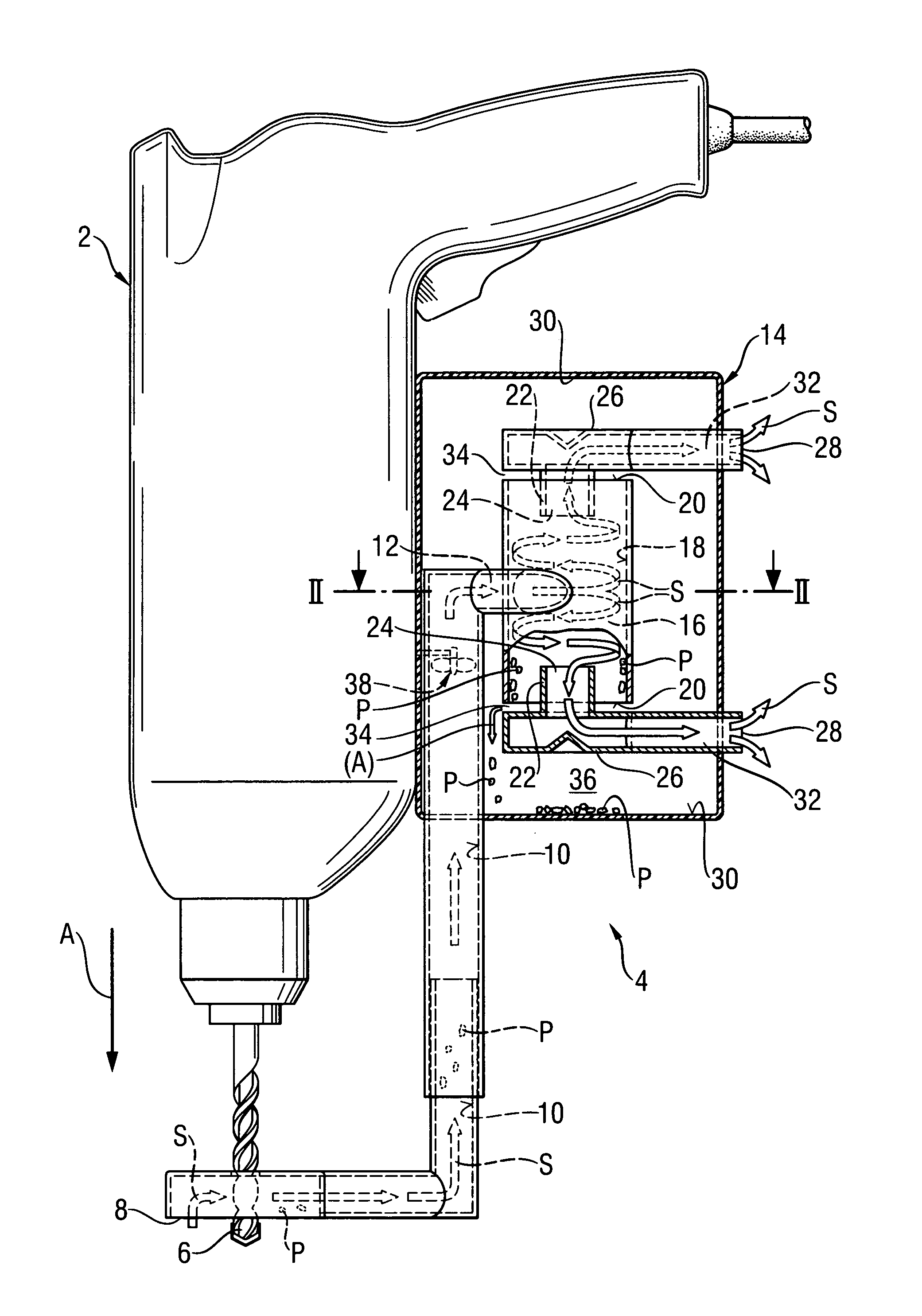
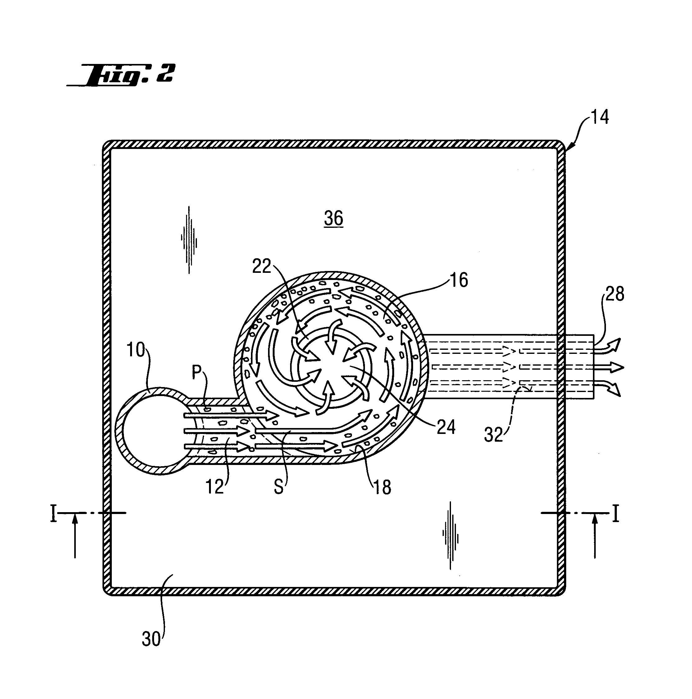
[0020]FIG. 1 shows a hand-held power tool 2, which is formed as a drilling or chiseling tool, together with a suction apparatus 4 which is releasably or permanently secured to the tool 2. The suction apparatus 4 includes a suction opening element 8 arranged on a working tool 6 that is formed as a drill. The suction opening element 8 is connected by a suction conduit 10 with a dirty air inlet 12 of a cyclone separator 14.

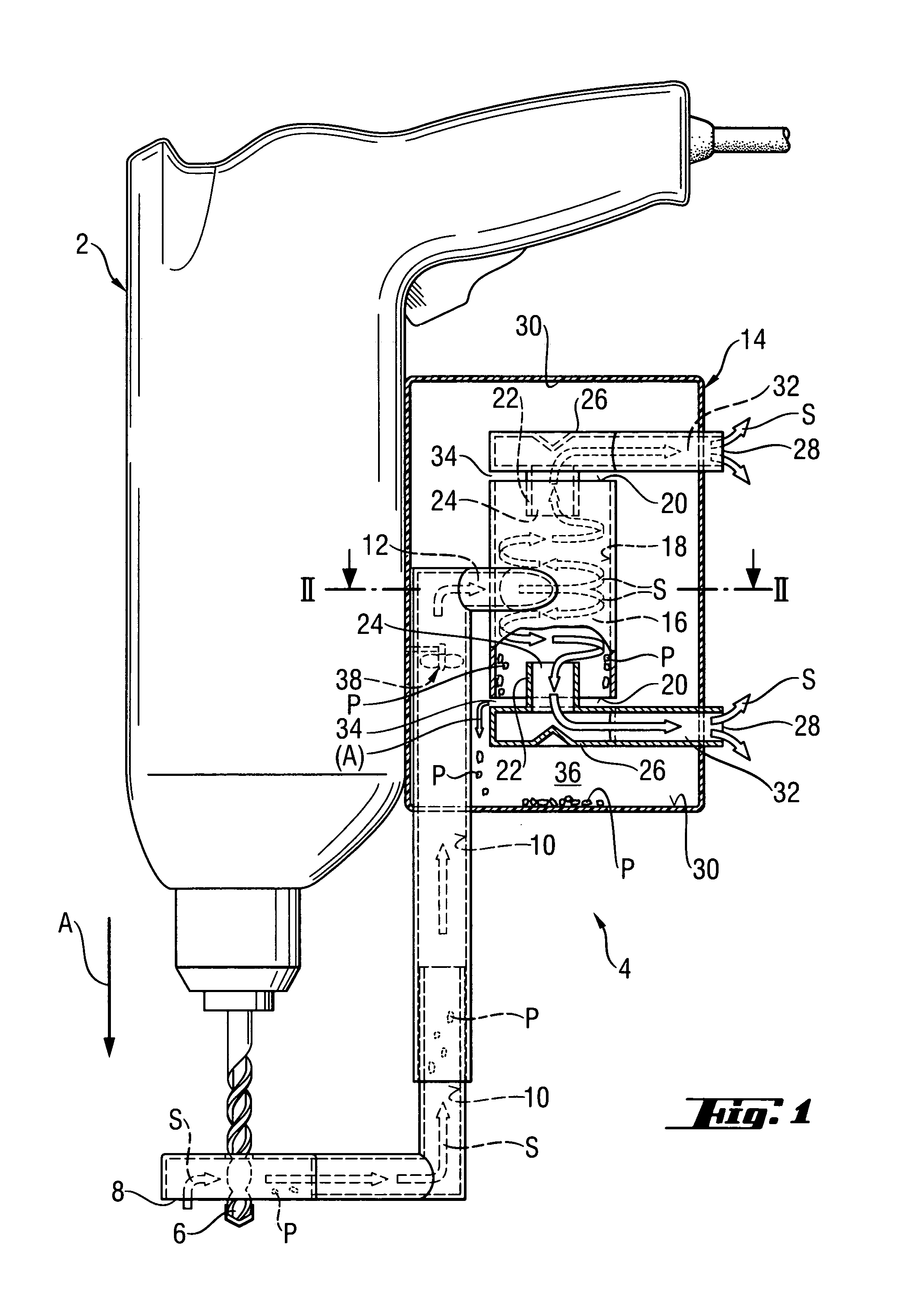
[0021]The cyclone separator 14 has a cylindrical vortex chamber 16 into which the dirty air inlet 12 opens substantially tangentially to an inner wall 18 of the vortex chamber 16, as particularly shown in FIG. 2.

[0022]As further shown in FIG. 1, the vortex chamber 16 has two open end sides 20. At both end sides 20, a respective immersion pipe 22 projects into the vortex chamber 16. Both immersion pipes 22 form at their open end, which project into the vortex chamber 16, a pure air extractor 24 located in the middle of the vortex chamber 16. Both immersion pipes 22 ar...


PUM

PropertyMeasurementUnit
volumeaaaaaaaaaa
gravity forceaaaaaaaaaa
heightaaaaaaaaaa

Abstract

A cyclone separator (14) for use in a suction apparatus (4) of a hand-held power tool (2) includes a dirty air inlet (12), a suction ventilator (38) for aspirating, through a suction opening (8) which is connected with the dirty air inlet (12), abrasion particle-carrying suction air, a pure air outlet for letting out purified air, a vortex chamber (16) arranged between the dirty air inlet (12) and the pure air outlet, with the dirty air inlet (12) opening substantially tangentially into the vortex chamber (16) for generating a swirling stream in a direction toward the pure air extraction element (24), a collection chamber (36), and particle outlet having at least two particle outlet openings and connecting the vortex chamber with a collection chamber (36), with the dirty air inlet opening into the vortex chamber between the two particle outlet openings.

Description

BACKGROUND OF THE INVENTION[0001]1. Field of Invention[0002]The present invention relates to a cyclone separator for use in a suction apparatus of a hand-held power tool, in particular of a motor-driven drilling or chiseling tool or of a saw. The cyclone separator includes a dirty air inlet and a suction ventilator for aspirating through suction opening means, which is connected with the dirty air inlet, suction air that carries abrasion particles produced during operation of the hand-held power tool. Further, there is provided a pure air outlet for letting out purified air. A vortex chamber is arranged between the dirty air inlet and the pure air outlet and into which the dirty air inlet opens substantially tangentially. By providing a pure air extractor connected with the pure air outlet, a swirling stream is generated. A particle outlet connects the vortex chamber with a collection chamber.[0003]2. Description of the Prior Art[0004]Cyclone separators of the type described above a...

Claims


Application Information

Patent Timeline
Patent Type & Authority Patents(United States)
IPC IPC(8): B01D45/12B01D50/00B04C3/04B04C3/06B04C5/12B04C5/185B04C5/187B04C9/00B23Q11/00
CPCB04C3/04B04C3/06B04C9/00B23Q11/0046B04C2009/004B04C2009/005A47L7/0095B04C5/12
Inventor MICHELE, VOLKERHEROLD, HEIKOSANCHEN, GUENTHER
Owner HILTI AG
Why Eureka
Try Eureka