Miniaturized ultra-wideband microstrip antenna

a microstrip antenna, ultra-wideband technology, applied in the direction of elongated active element feed, resonance antenna, antenna earthing, etc., can solve the problems of inability to realize omni-directional characteristics of antennas, inability to accommodate, and high-speed data transmission. achieve the effect of improving the wideband characteristics of antennas

Active Publication Date: 2008-01-29
SAMSUNG ELECTRONICS CO LTD
View PDF23 Cites 21 Cited by
  • Summary
  • Abstract
  • Description
  • Claims
  • Application Information

AI Technical Summary

Benefits of technology

[0015]It is another aspect of the present invention to provide a miniaturized UWB microstrip antenna having improved narrowband and multi-harmonic features, by employing a main radiating element and a sub-radiating element connected to the main radiating element.
[0016]It is still another aspect of the present invention to provide a miniaturized UWB microstrip antenna with improved wideband-matching properties in a desired frequency range through a specific notch structure constructed of a main radiating element and a sub-radiating element connected thereto.
[0020]According to another aspect of the present invention, an upper end of the main radiating element has a rectangular shape, the sub-radiating elements are symmetrically arranged with respect to the main radiating element, and an upper end of each sub-radiating element preferably has a rectangular shape among other possible shapes in order to reduce the size of the antenna.
[0043]According to an aspect of the present invention, the antenna further includes at least one additional sub-radiating element disposed at a predetermined position improving wideband characteristics of the antenna.
[0050]According to another aspect of the present invention, the antenna further includes at least one additional sub-radiating element disposed at a predetermined position improving wideband characteristics of the antenna.

Problems solved by technology

As already known, impulse radio communications, unlike existing narrowband communications, use an ultra-wideband frequency band and transmit high-speed data consuming much power.
However, the antenna could not accommodate the UWB waveform, and the patch antenna, being a single patch antenna by nature, is incapable of realizing omni-directional characteristics of antennas.
In addition, when mounted in small-sized mobile communication equipment, the antenna's directivity interferes with smooth and proper communication, and thus, at least two antennas are required.
It is practically impossible to implement a wideband matching circuit having a bandwidth greater than 3:1 in a relatively low (less than 5 GHz) frequency domain.
Also, the disclosed antenna has a dual plane structure and thus, process cost thereof is higher than a single plane antenna.
Although this type of antenna has electric elements to meet the requirements of pulse communications in a desired frequency range, it is not proper to be miniaturized.
Thus, the practicability of the antenna is basically limited.
Moreover, because the resistor is employed in order to improve the VSWR in a low frequency range, it is not easy to maintain high reliability of the antenna.

Method used


Image

  • Miniaturized ultra-wideband microstrip antenna
  • Miniaturized ultra-wideband microstrip antenna
  • Miniaturized ultra-wideband microstrip antenna

Examples


Embodiment Construction

[0073]Reference will now be made in detail to the embodiments of the present invention, examples of which are illustrated in the accompanying drawings, wherein like reference numerals refer to the like elements throughout. The embodiments are described below to explain the present invention by referring to the figures.

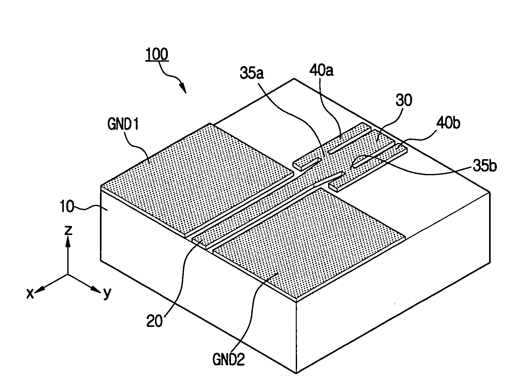
[0074]FIG. 6 is a perspective view of a CPW (Coplanar waveguide) fed microstrip antenna according to an aspect of the present invention; FIG. 7 is a perspective view of a GCPW (Ground coplanar waveguide) fed microstrip antenna according to another aspect of the present invention; and FIG. 8 is a perspective view of a microstrip fed antenna according to another aspect of the present invention

[0075]As shown in FIGS. 6 to 8, the miniaturized ultra-wideband microstrip antenna 100 of the present invention includes a dielectric substrate 10, a feed line 20, a main radiating element 30, a plurality of connection plates 35a, 35b, a plurality of sub-radiating elements 40a, 40b,...


PUM


Abstract

A miniaturized ultra-wideband microstrip antenna, includes: a dielectric substrate; a feed line disposed on the dielectric substrate, and supplying an electromagnetic energy supplied from an external power source; a main radiating element radiating the electromagnetic energy inputted by the feed line; and at least one sub-radiating element disposed in proximity to the main radiating element for multi-radiation. Also, the antenna further includes at least one connection plate electrically connecting the main radiating element to at least one of the sub-radiating elements. The miniaturized ultra-wideband microstrip antenna can also be made ultralight, and include additional sub-radiating elements besides the main radiating element, whereby multi-radiation in UWB's range can be attained.

Description

CROSS-REFERENCE TO RELATED APPLICATION[0001]This application claims the benefit under 35 U.S.C. § 119 from Korean Patent Application No. 2004-00384, filed on Jan. 5, 2004 in the Korean Intellectual Property Office, the disclosure of which is incorporated herein by reference.BACKGROUND OF THE INVENTION[0002]1. Field of the Invention[0003]The present invention relates in general to a wideband impulse transmitting / receiving antenna for use with communication systems employing electromagnetic impulses, such as, UWB (Ultra Wideband) communications. More specifically, the present invention relates to a miniaturized UWB microstrip antenna having excellent wideband characteristics by changing the notch structure of a main radiating element and a sub-radiating element connected to the main radiating element.[0004]2. Description of the Related Art[0005]UWB uses pulses which have the attribute of being spread over a frequency range measured in 3.1-10.6 gigahertz (GHz) for transmitting digital ...

Claims


Application Information

Patent Timeline
Patent Type & Authority Patents(United States)
IPC IPC(8): H01Q1/38H01Q5/00H01Q13/08H01Q9/40
CPCH01Q1/38H01Q5/50H01Q9/40H01Q13/08
Inventor MYOUNG, SOUNG-HOKWON, DO-HOONLEE, SEONG-SOO
Owner SAMSUNG ELECTRONICS CO LTD
Why Eureka
Try Eureka