Optical fiber cables for wellbore applications

a technology of optical fiber cables and wellbores, applied in the direction of optical fibers, instruments, mechanical structures, etc., can solve the problems of optical fibers that cannot be characterized by comparable stretch/strain characteristics, lack of comparable stretch/strain characteristics, and the possibility of volatilization of volatile organic compounds

Active Publication Date: 2008-01-29
SCHLUMBERGER TECH CORP
View PDF19 Cites 133 Cited by
  • Summary
  • Abstract
  • Description
  • Claims
  • Application Information

AI Technical Summary

Problems solved by technology

Optical fibers present certain difficulties such as degradation due to hydrogen exposure, particularly at high temperatures, lack of comparable stretch / strain characteristics as compared with other cable elements, the possibility of volatilization of volatile organic compounds (VOCs) in coatings or other polymeric protective layers on the optical fibers, and hydrolytic attack against glass in the presence of water.
However, when the elongation stress is removed from the cable the polymeric material does not return to its original length, which leads to local stress points and causes signal attenuation.
Thus, a typical mechanical limitation for acceptable performance of optical fiber based cables is the amount of stretch a cable can withstand.

Method used


Image

  • Optical fiber cables for wellbore applications
  • Optical fiber cables for wellbore applications
  • Optical fiber cables for wellbore applications

Examples


first embodiment

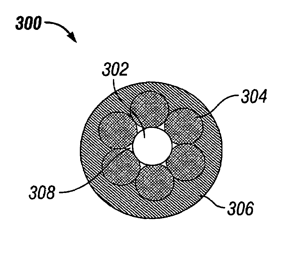
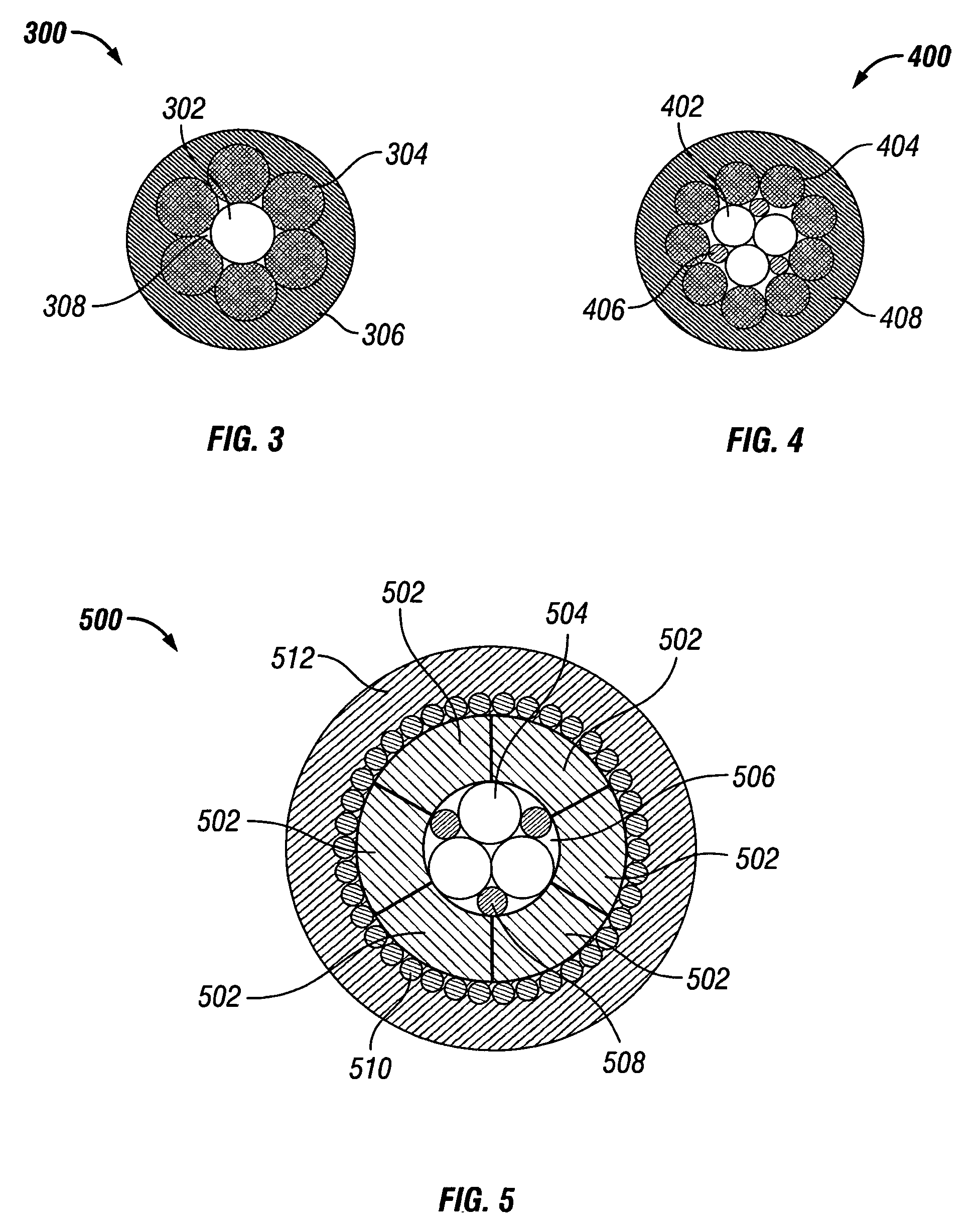
[0034]FIG. 3 illustrates, in cross section, an optical fiber conductor bundle according to the present invention. The conductor bundle 300 includes an optical fiber 302 centrally positioned on the center axis of the conductor bundle 300, and a plurality of metallic conductors 304 (only one indicated) helically positioned around the optical fiber 302. A polymeric insulating material 306 surrounds the metallic conductors 304. Further, the volume between the optical fiber 302 and metallic conductors 304 may be filled with an interstitial filler 308. The conductor bundle 300 may serve as a central conductor bundle, such as the conductor bundle 102 of cable 100 as depicted in FIG. 1. Also, the conductor bundle 300 may be positioned in a cable as one or more outer conductor bundles, for example, by replacing the outer conductor bundles 104 in FIG. 1.

[0035]FIG. 4 is a cross-sectional view of a second illustrative embodiment of the present invention. The conductor bundle 400 has a plurality...

sixth embodiment

[0039]Referring to FIG. 8, which illustrates the present invention, conductor bundle 800 includes a central optical fiber 802 positioned on the central axis of the conductor bundle 800. One or more optical fibers 804 (only one indicated) and a plurality of metal conductors 806 (only one indicated) are positioned helically around the central optical fiber 802. The conductor bundle further includes polymeric insulation material filler 808. The interstitial space 810 formed between the central optical fiber 802, the metal conductors 806, and optical fibers 804, may further be filled with an interstitial filler. The conductor bundle 800 may be employed in cable configuration as central and outer conductor bundles.

[0040]FIG. 9 depicts, in cross-section, a seventh illustrative embodiment of the present invention. The conductor bundle 900 may include any combination of optical fibers 902, metallic conductors 904 (only one indicated), polymeric insulating material 906, or other components a...

eighth embodiment

[0041]Referring to FIG. 10, which illustrates the present invention. The conductor bundle 1000 according to the present invention may further include a jacket encasement 1002 encasing the polymeric insulating material 1004, where the jacket encasement 1002 provides further protection for the conductor bundle 1000. The conductor bundle can include metallic conductors 1006 (only one indicated), optical fibers 1008 (only one indicated), interstitial fillers 1010 (only one indicated), a polymeric insulating material 1004, or any other components in accordance with the invention. Copper or other metallic tape may be used to form the jacket encasement 1002. The jacket encasement 1002 may also be an extrusion of tin and gold alloy solder, any other extrudable metal or metal alloy, or welded metallic tube that is drawn and shaped around the outer periphery of the polymeric insulating material 1004. When metallic tape is used, the seams of the tape may optionally be overlapped or crimped, an...


PUM


Abstract

A cable which includes conductor bundles prepared from at least one optical fiber positioned either centrally or helically about the center axis of the bundle, metallic conductors helically positioned around the bundles center axis, and a polymeric insulation material. A method of making a cable including forming a conductor bundle by placing helically positioned conductors and optical fibers about the periphery of a central optical fiber or metallic conductor, encasing the conductors, optical fibers, in a polymeric insulation material, and grouping the conductor bundles together.

Description

[0001]This patent application is a non-provisional application of provisional application Ser. No. 60 / 572,396 filed May 19, 2004.BACKGROUND OF THE INVENTION[0002]1. Field of the Invention[0003]This invention relates to electrical and / or optical cables and, in particular to wireline cables having optical fiber(s) therein.[0004]2. Description of the Related Art[0005]In the petroleum industry, wireline cables are used to support tools, provide power, and collect data downhole from well-bores. In the case of data collection, the use of optical fibers in electric and / or optical cable offers the potential to carry greater amounts of information than conventional conductors. This is important since at a set diameter, factors such as maximizing data transfer, cable strength, power capacity, and environmental durability are critical to optimum cable design. Optical fibers present certain difficulties such as degradation due to hydrogen exposure, particularly at high temperatures, lack of com...

Claims


Application Information

Patent Timeline
Patent Type & Authority Patents(United States)
IPC IPC(8): G02B6/44
CPCG02B6/4413G02B6/4416
Inventor VARKEY, JOSEPHMYDUR, RAVICHARANSAIT, NOORWIJNBERG, WILLEMKUNATHIKOM, SUMITRADARPI, MONICA
Owner SCHLUMBERGER TECH CORP
Why Eureka
Try Eureka