Rankine cycle and steam power plant utilizing the same

Inactive Publication Date: 2008-02-05
SIEMENS ENERGY INC
View PDF22 Cites 8 Cited by
  • Summary
  • Abstract
  • Description
  • Claims
  • Application Information

AI Technical Summary

Problems solved by technology

This expansion is not completely isentropic due to the expected inefficiencies in the turbine design.

Method used


Image

  • Rankine cycle and steam power plant utilizing the same
  • Rankine cycle and steam power plant utilizing the same
  • Rankine cycle and steam power plant utilizing the same

Examples


first embodiment

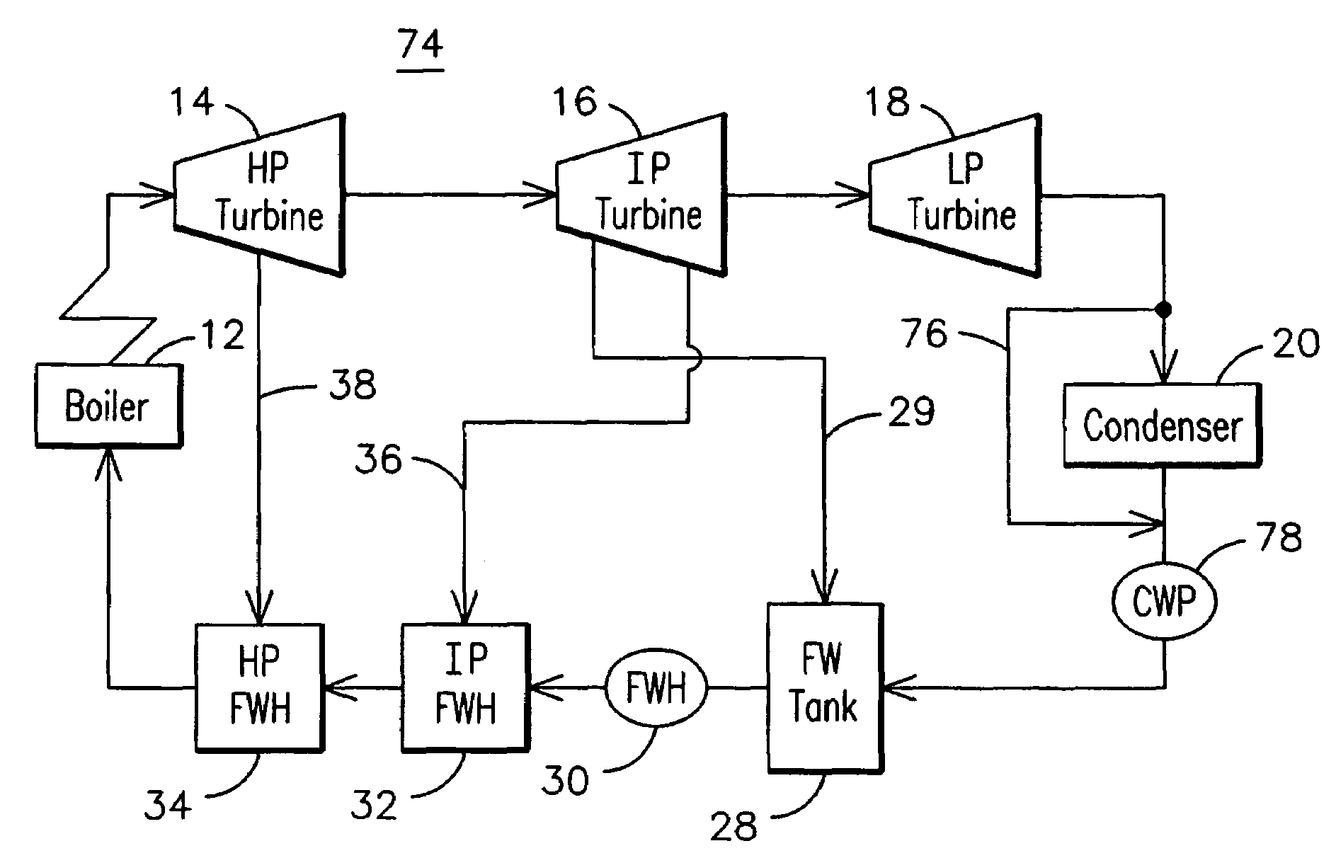
[0026]A first embodiment is illustrated in FIG. 5 wherein a steam power plant 74 implementing an improved Rankine cycle is provided with a bypass 76 of condenser 20 in order to eliminate the need for low-pressure feedwater heaters. Note that similar components used in various embodiments are numbered consistently in respective figures. At least some of the steam from the exhaust of the low-pressure turbine 18 is bypassed around condenser 20. The mass flow of the bypass steam may be selected such that the conditions downstream of the condensate pump 78 are the same as they were downstream of the low-pressure feedwater heaters in the prior art plant 10 of FIG. 1. The condensate pump 78 receives a steam / water mixture, thus pump 78 must be a multiphase pump. FIG. 5 is drawn to show that all low-pressure feedwater heaters have been eliminated. Other embodiments may eliminate only one or more of the low-pressure feedwater heaters while retaining at least one low-pressure heater. One may a...

second embodiment

[0029]A second embodiment illustrated in FIG. 7 also has an inlet connected to the energy extraction portion of the plant and an outlet connected to the energy addition portion of the plant. In this embodiment, a steam power plant 80 is provided with a high-pressure steam extraction connection 82 for injecting high-pressure steam into the feedwater system at a point 84 downstream of the high-pressure feedwater heater 34 and upstream of the boiler 12. The high-pressure steam extraction connection inlet 86 draws steam from the high-pressure section of the steam system proximate the high-pressure turbine 14. One may appreciate that the exact point of extraction may vary depending upon the desired supply pressure. FIG. 7 shows the inlet 86 as a steam bleed directly from one of the stages of the high-pressure turbine 14, although it may be appreciated that any other point proximate the high-pressure turbine 14 may be selected for a particular application. The steam injection will create ...

third embodiment

[0031]FIG. 9 illustrates a steam power plant 90 wherein all high pressure feedwater heaters have been replaced by a high pressure steam injection connection 92 and an associated downstream multiphase pump 94. Here again the variables are the steam extraction pressure and the steam quality after mixing, as shown in FIG. 10. The optimum conditions for this embodiment are an extraction pressure of 1,000 psia and a steam quality after mixing of 20%, resulting in a plant efficiency gain of 0.37%. At these conditions the enthalpy into the boiler 12 is larger than in the modeled base plant, thereby requiring less heat addition in the boiler 12. This results in an increase in plant efficiency even after subtracting the added power load of the multiphase pump 94.


PUM


Abstract

A steam power plant (100) implementing an improved Rankine cycle (55) wherein steam is injected (82, 96) directly into the energy addition portion of the plant, and the resulting two-phase flow is pressurized by multiphase pumps (88, 98). By relying more heavily on pump pressurization than on a temperature difference for energy injection, plant efficiency is improved over prior art designs since energy injection by pump pressurization results in less irreversibility than energy injection by temperature difference. Direct steam injection and multiphase pumping may be used to bypass the condenser (20), to replace any one or all of the feedwater heaters (24, 32, 34), and / or to provide additional high-pressure energy addition.

Description

FIELD OF THE INVENTION[0001]This invention relates generally to the field of vapor cycles and more particularly to steam power plants operating on a Rankine cycle.BACKGROUND OF THE INVENTION[0002]Basic elements of a conventional steam power plant 10 are illustrated in schematic form in FIG. 1. A boiler 12 burns a combustible fuel to provide heat energy to convert feedwater into saturated or superheated steam for delivery to a high-pressure turbine 14. The steam is expanded through the turbine 14 to turn a shaft that powers an electrical generator (not shown). The steam is then directed in sequence through an intermediate pressure turbine 16 and a low-pressure turbine 18 where additional shaft energy is extracted. The spent steam leaving the low-pressure turbine 18 is converted back to water in condenser 20. A condensate pump 22 delivers water from the condenser 20 to a low-pressure feedwater heater 24. The feedwater heater 24 is a heat exchanger that adds energy to the water as a re...

Claims


Application Information

Patent Timeline
Patent Type & Authority Patents(United States)
IPC IPC(8): F01K13/00F01K7/40F01K19/04F01K21/00
CPCF01K7/40F01K19/04F01K21/00
Inventor CUNNINGHAM, CARLA I.BRIESCH, MICHAEL S.
Owner SIEMENS ENERGY INC
Why Eureka
Try Eureka