Vapour and water separator

A technology of steam-water separator and separation cylinder, which is applied in the direction of separation method, dispersed particle separation, chemical instruments and methods, etc., can solve the problem of low critical flow velocity of steam-water separator, and achieve the improvement of critical inlet steam flow velocity, uniform steam distribution, and drainage good effect

Active Publication Date: 2006-05-31
RES INST OF NUCLEAR POWER OPERATION
View PDF0 Cites 18 Cited by
  • Summary
  • Abstract
  • Description
  • Claims
  • Application Information

AI Technical Summary

Problems solved by technology

The critical flow rate of this steam-water separator is low, and the steam-water separation effect needs to be further improved. Moreover, due to the use of the secondary separato

Method used


Image

  • Vapour and water separator
  • Vapour and water separator
  • Vapour and water separator

Examples


Embodiment Construction

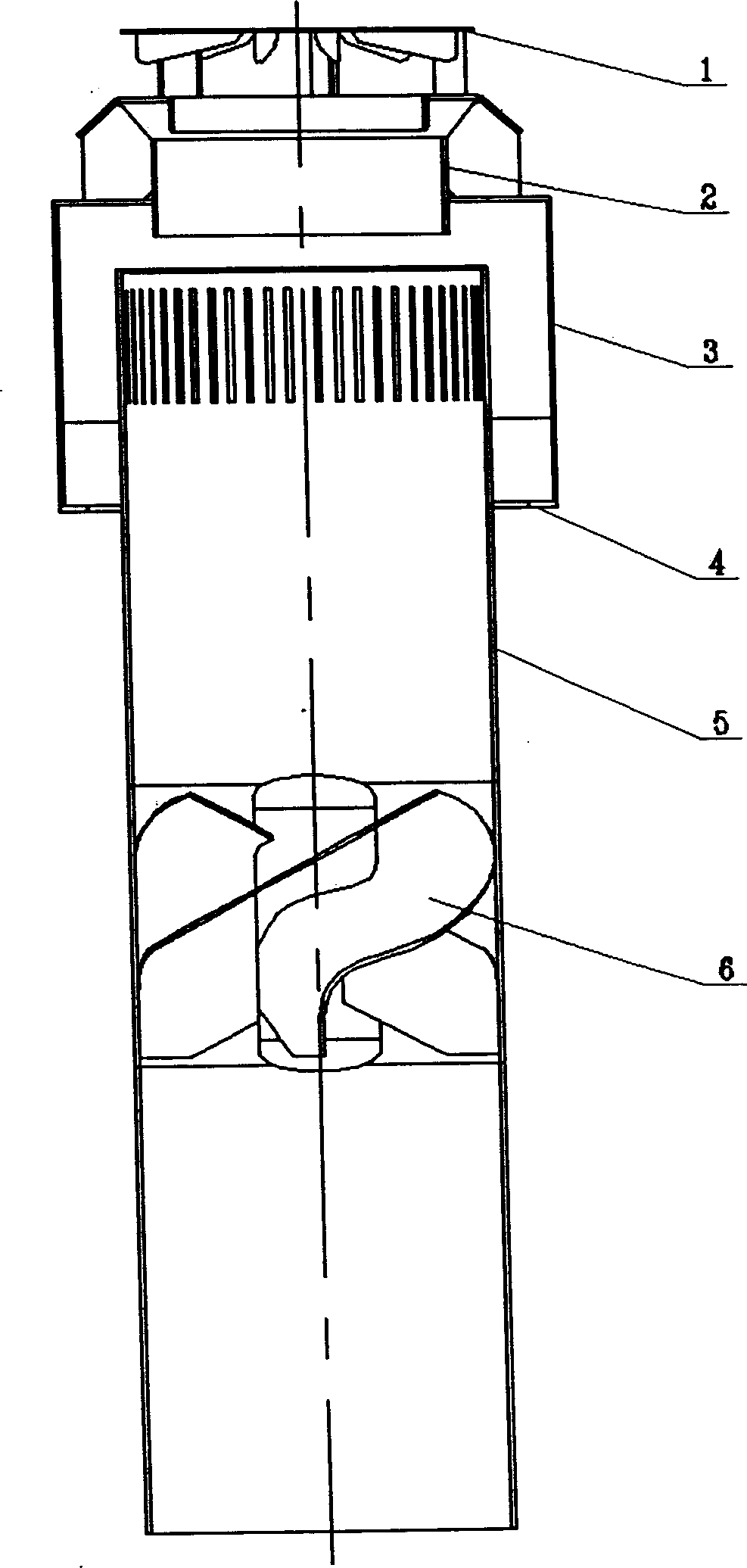
[0018] Such as figure 1 As shown, the steam-water separator includes a separation cylinder 5 and a sleeve 3 sleeved outside the separation cylinder 5. The lower part of the sleeve 3 is provided with a hydrophobic restrictor ring 4, and the central column in the separation cylinder 5 is provided with double inclined blades 6. The entire steam generator is filled with water below the center of the double inclined blades. The length of the sleeve 3 of the present invention is relatively short, and the entire sleeve 3 including the hydrophobic restrictor ring 4 is located above the water space, so that bypass steam can be avoided. Entering the descending passage of the steam generator, eliminating the downcarrying phenomenon of the general steam-water separator, the bottom of the sleeve 3 is welded with the hydrophobic flow-limiting ring 4, which can limit the flow rate of water and prevent the steam from flowing out. The top of the separation cylinder 5 is provided with a steam ...


PUM


Abstract

A steam-water separator for the steam generator in nuclear power plant and the boiler in steam power plant is composed of a separating cylinder with central column and dual oblique blades installed to said central column, a sleeve barrel outside the separating cylinder with a hydrophibic flow limiting ring at its bottom end, a steam outlet barrel above said separating cylinder, and a diverter cover above said steam outlet barrel and with radiating blades. Its advantage is high critical flow seed of steam and separating efficiency.

Description

technical field [0001] The invention relates to equipment for dehumidifying gas or steam, in particular to a steam-water separator in a steam generator of a nuclear power plant or a drum boiler of a thermal power plant. Background technique [0002] The steam-water separator is located under the dryer and the gravity separation space in the steam generator of the nuclear power plant or the steam drum boiler of the thermal power station. Dry saturated steam ensures the safe and economical operation of the steam turbine. The structure of the steam generator steam-water separator in the existing nuclear power plant is as follows: figure 2 As shown, this steam-water separator includes a separation cylinder 10, an outer cylinder 9 is arranged outside the separation cylinder 10, a tangential drainage port 8 is arranged on the upper part of the outer cylinder 9, and an annular drainage channel 13 is arranged outside the outer cylinder 9, and the annular drainage channel 13 The lo...

Claims


Application Information

Patent Timeline
IPC IPC(8): B01D53/26B01D45/14
Inventor 薛运奎陈军亮左超平王先元
Owner RES INST OF NUCLEAR POWER OPERATION
Why Eureka
Try Eureka