Modular underbody for a motor vehicle

a technology for motor vehicles and modules, applied in the direction of roofs, transportation and packaging, vehicle arrangements, etc., can solve the problems of high manufacturing cost, inability to use the side rails of one automobile for other automobiles of a different length or size,

Active Publication Date: 2008-02-05
MAGNA INTERNATIONAL INC
View PDF44 Cites 40 Cited by
  • Summary
  • Abstract
  • Description
  • Claims
  • Application Information

AI Technical Summary

Benefits of technology

[0007]The invention also provides a method of forming a frame assembly comprising providing a pair of laterally spaced, longitudinally extending central side-rail structures, each having a top and a side; forming a pair of tubular hydroformed first side rail members by a method comprising, providing a tubular metallic blank having a tubular metallic wall, placing the tubular metallic blank into a die cavity of a die assembly, the die cavity having die surfaces, and providing a high pressure fluid into an interior of the blank to expand the metallic wall of the blank outwardly into...

Problems solved by technology

Thus, side rails for one automobile may not be capable of being used for other automobiles of a different length or size.
Also, automobile fra...

Method used


Image

  • Modular underbody for a motor vehicle
  • Modular underbody for a motor vehicle
  • Modular underbody for a motor vehicle

Examples


Embodiment Construction

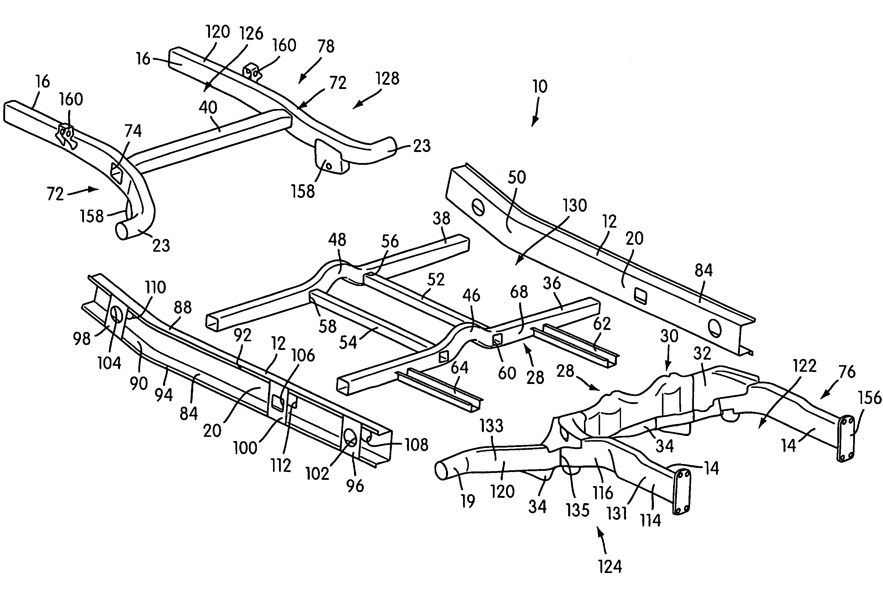
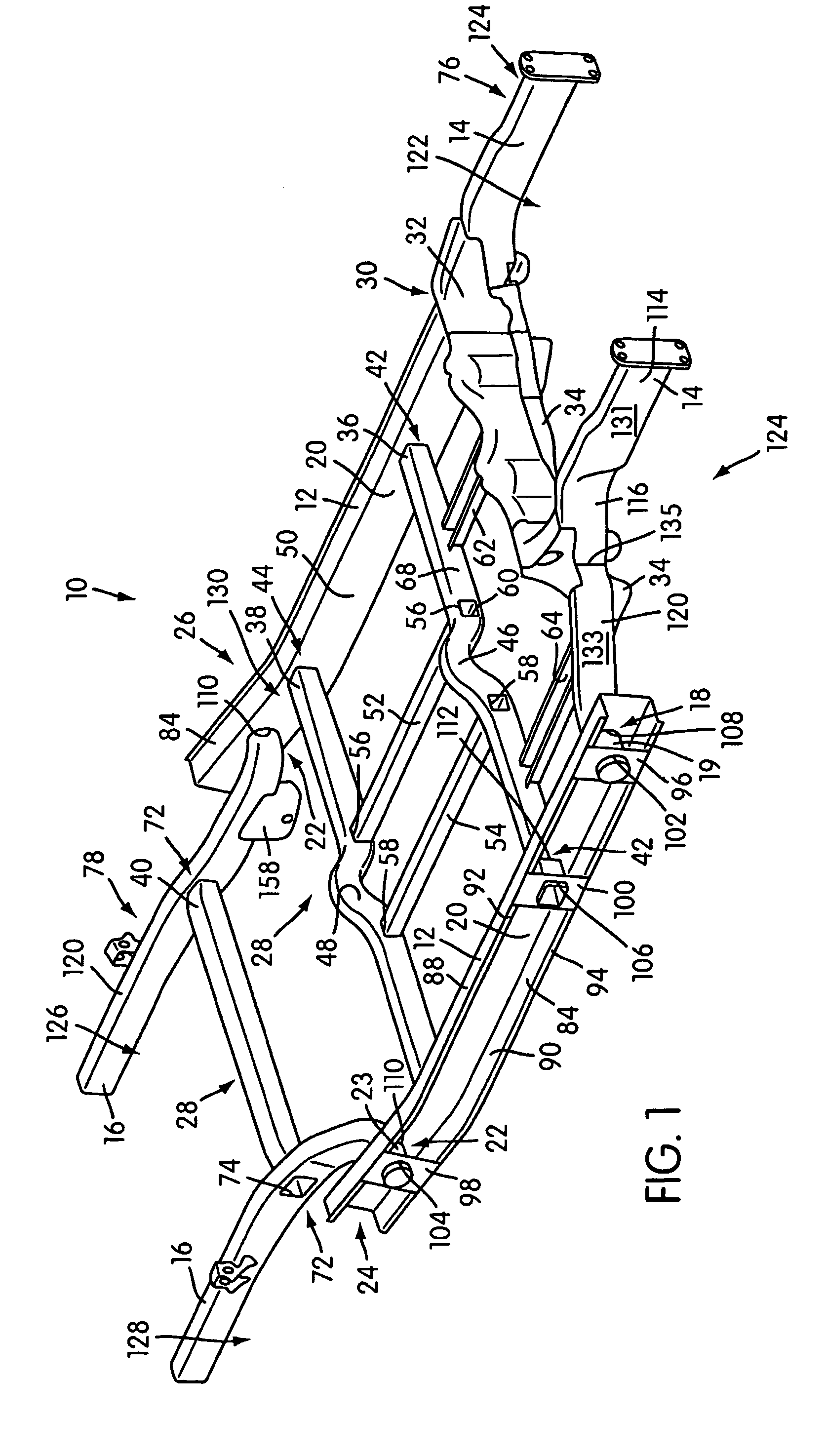
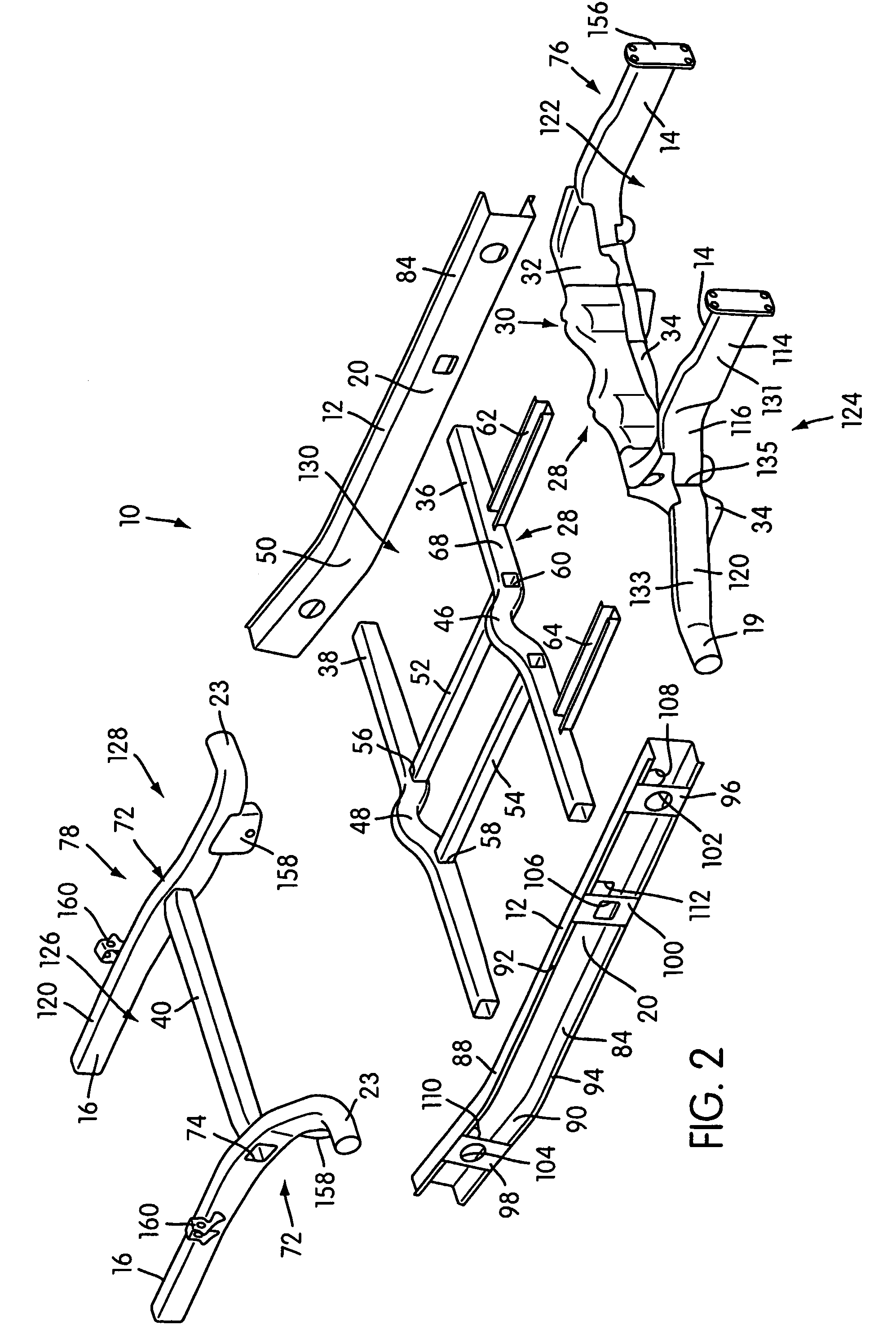
[0023]FIG. 1 shows an illustrated embodiment of a modular underbody frame 10 for a motor vehicle constructed according to the principles of the present invention. The FIG. 2 shows the frame 10 in partially exploded view. The frame 10 includes a pair of laterally spaced, longitudinally extending central side rail structures 12, a pair of forward side rail structures forming a front module 76, and a pair of rearward side rail structures forming a rearward module 78.

[0024]The use of modules 76 and 78 with central side rail structures 12 permits great versatility in forming frame 10 and in using these components for forming other frames. For example, the modules 76 and 78 may be used together or separate in the manufacturing of other frames with other central side rail structure configurations. Thus, the use of modules 76 and 78 may achieve great savings in the inclusion of the modules 76 and 78 into other motor vehicle frames. Additionally, the modules 76 and 78 can be used with differ...


PUM


Abstract

A module for a frame for a motor vehicle with a pair of laterally spaced, longitudinally extending central side rail structures. The module including a pair of tubular hydroformed side rail members and a laterally extending connecting structure connected between the pair of side rail members to secure the pair of side rail members in laterally spaced, fixed relation to one another. Each first portion of the pair of side rail members extending longitudinally and each second portion of the pair of side rail members extending laterally relative to the respective first portion and each second portion having an end being constructed and arranged to form a joint with a portion of a respective central side rail structure such that the end of each of the pair of side rail members extends generally laterally through a side of the respective central side rail structure.

Description

[0001]This application is the National Phase of International Application PCT / US02 / 36177 filed Nov. 12, 2002 which designated the U.S. and that International Application was published in English under PCT Article 21(2) on Aug. 28, 2003 as International Publication Number WO 03 / 1070543A1. PCT / US02 / 36177 claims priority to U.S. Provisional Application No. 60 / 331,186, filed Nov. 9, 2001. Thus, the subject nonprovisional application claims priority to U.S. Provisional Application No. 60 / 331,186, filed Nov. 9, 2001. The entire contents of these applications are incorporated herein by reference, respectively.FIELD OF THE INVENTION[0002]The present invention is related to structural frames. In particular, the illustrated embodiment of the present invention relates to frames for motor vehicles.BACKGROUND OF THE INVENTION[0003]Frames for automobiles are commonly made with a pair of side rails that extend the entire length of the automobile. Thus, automobiles of different length will have sid...

Claims


Application Information

Patent Timeline
IPC IPC(8): B62D21/07B62D21/15B62D21/02B62D21/12B62D23/00B62D27/02B62D29/00B62D65/04
CPCB62D21/02B62D21/07B62D21/12B62D23/005B62D25/025B62D27/02B62D29/007B62D65/04
Inventor HORTON, FRANK A.GABBIANELLI, GIANFRANCOASHLEY, RICHARD D.CUMMING, DAVID
Owner MAGNA INTERNATIONAL INC
Why Eureka
Try Eureka