
IC card wrong insertion preventing mechanism and IC card connector having the same

a technology of preventing mechanism and ic card, which is applied in the direction of conveying record carriers, coupling device connections, instruments, etc., can solve problems such as damage to contact terminals, and achieve the effect of avoiding plurality of ic cards

Active Publication Date: 2008-02-05
YAMAICHI ELECTRONICS
View PDF84 Cites 14 Cited by
  • Summary
  • Abstract
  • Description
  • Claims
  • Application Information

AI Technical Summary

Benefits of technology

The invention provides an IC card wrong insertion preventing mechanism and an IC card connector with the mechanism. The mechanism includes a wrong insertion restraining member that can be rotated to guide the leading end of a first or second IC card in the correct orientation when it is inserted. The mechanism also includes an urging member to push the restraining member in the ejecting direction and a locking member to keep the restraining member in the correct position when the second card is inserted. The mechanism ensures that multiple IC cards cannot be inserted in the wrong direction, preventing mistaken insertion. The connector includes the mechanism and can accommodate different types of IC cards while preventing mistaken insertion.

Problems solved by technology

As a result, the first IC card may be inserted in the inverted insertion state by mistake, which can result in damage to contact terminals.

Method used


Image

  • IC card wrong insertion preventing mechanism and IC card connector having the same
  • IC card wrong insertion preventing mechanism and IC card connector having the same
  • IC card wrong insertion preventing mechanism and IC card connector having the same

Examples


first embodiment

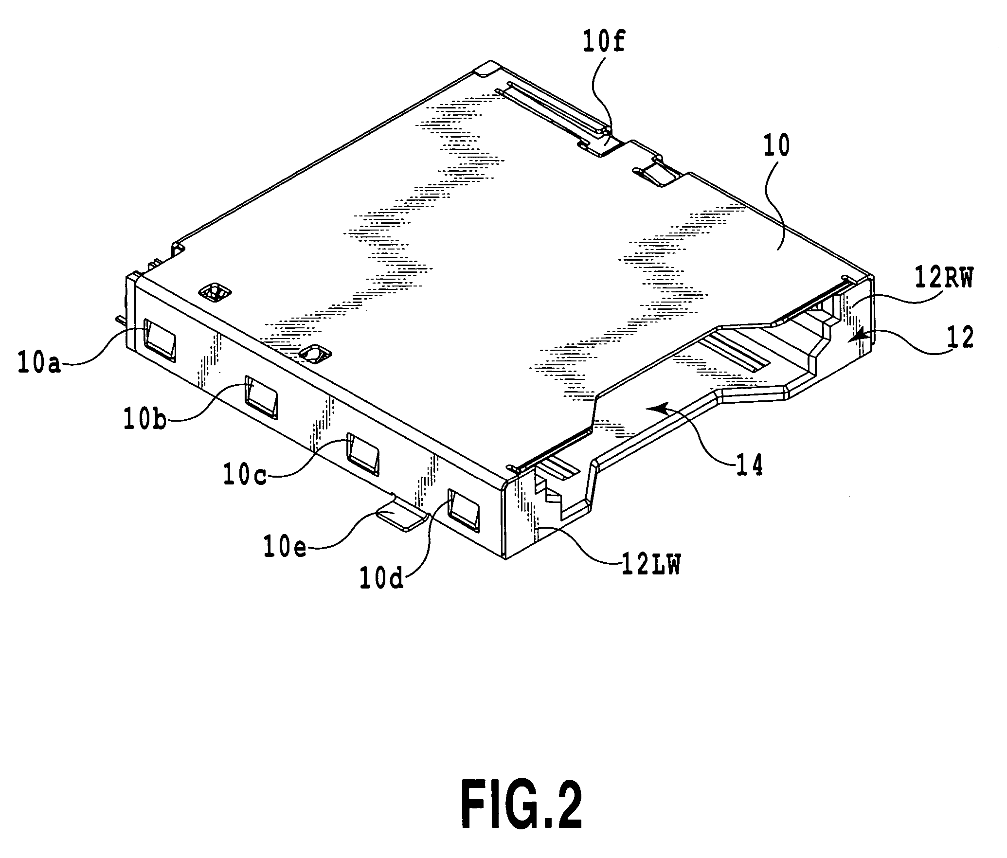
[0046]FIG. 2 shows the external appearance of an IC card connector according to the present invention.

[0047]The IC card connector shown in FIG. 2 is disposed in a predetermined electronic apparatus, including e.g., a cellular phone, PDA or camera.

[0048]The IC card connector shown in FIG. 2 establishes electrical connection between an electrode portion of any of following memory cards as an IC card removably contained in a card accommodation portion thereof, e.g., an SD CARD (secure digital card; trademark) MC as a first IC card or a MINI SD CARD (trademark) SMC as a second IC card (see FIGS. 11A and 12) and a connection terminal portion of a signal input / output substrate disposed in the predetermined electronic apparatus. The IC cards are not limited to the SD CARD and the MINI SD CARD as mentioned above, and they may be two types of cards having different transverse widths arbitrarily selected from among MMCs (multimedia cards; trademark), memory cards incorporating a flash memory ...

second embodiment

[0098]FIG. 14 shows an IC card connector according to the invention.

[0099]In the embodiment shown in FIG. 2, the wrong insertion restraining member 22 of the card wrong insertion preventing mechanism prevents wrong insertion of a MINI SD CARD SMC in a configuration in which the member is rotatably supported on the base member 12. In the embodiment shown in FIG. 14, a card wrong insertion preventing movable plate 44 of a card wrong insertion preventing mechanism prevents wrong insertion of a MINI SD CARD SMC in a configuration in which the plate is supported such that it can be moved up and down with reference to a base member 42. In FIG. 15 which will be described later, elements identical to constituent elements of the embodiment shown in FIG. 2 are indicated by like reference numerals and will not be described to avoid duplication.

[0100]Such an IC card connector is also disposed in a predetermined electronic apparatus such as a portable telephone, a PDA or a camera.

[0101]The IC ca...


PUM


Abstract

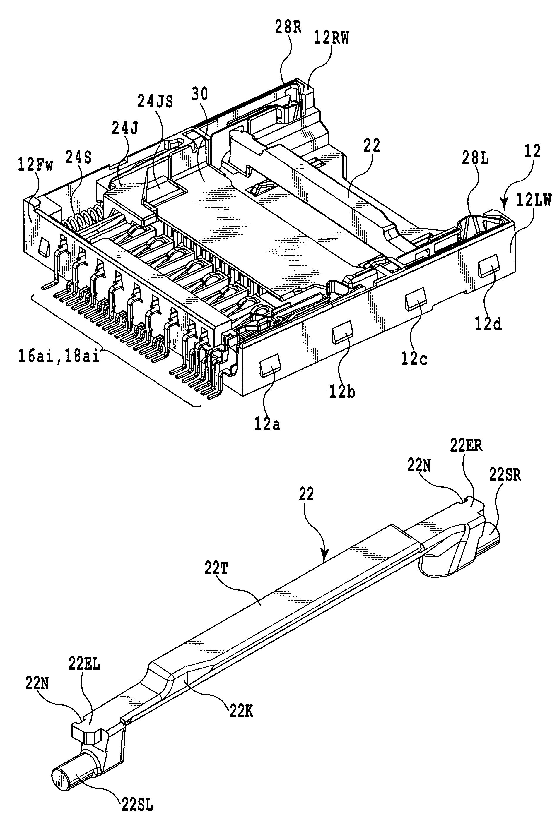
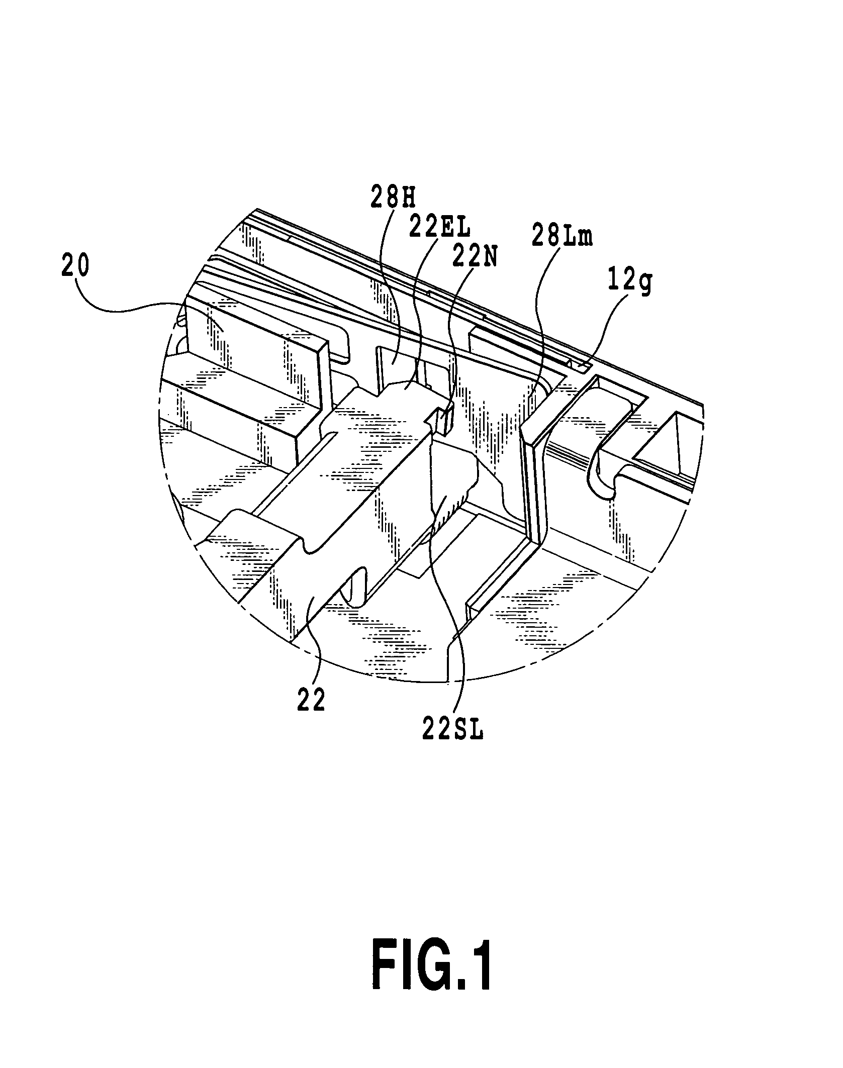
Engaging portions of a wrong insertion restraining member for restraining wrong insertion of a MINI SD CARD have respective notches engaging the outer edges of openings of locking members.

Description

[0001]This application claims the benefit of Japanese Patent Application No. 2005-356433 filed Dec. 9, 2005, which is hereby incorporated by reference herein in its entirety.BACKGROUND OF THE INVENTION[0002]1. Field of the Invention[0003]The present invention relates to an IC (integrated circuit) card wrong insertion preventing mechanism and an IC card connector incorporating the mechanism in a multiple card accommodation portion thereof.[0004]2. Description of the Related Art[0005]In general, the functions of electronic apparatus are expanded in various ways by mounting IC cards such as MMCs (multimedia cards (trademark)), SD (secure digital) cards, and MINI SD CARDs (trademark) in the apparatus through IC card connectors.[0006]In order to allow a plurality of IC cards having different shapes to be mounted and used in a single electronic apparatus, for example, as shown in Japanese Patent Application Laid-open Nos. 2004-311416 and 2004-193111, a proposed IC card connectors are prov...

Claims


Application Information

Patent Timeline
Patent Type & Authority Patents(United States)
IPC IPC(8): H01R24/00
CPCG06K7/0034G06K13/08G06K13/0887H01R13/6456
Inventor TAKAI, YOSUKESHIMIZU, OSAMUHENMI, KIYOTAKA
Owner YAMAICHI ELECTRONICS
Learn More