[0006] The invention is based on the object of improving a plug-in connection of the type mentioned initially such that the above-described disadvantages are reliably avoided; in particular, firstly, the union nut is reliably prevented from becoming detached by means of vibration movements and, secondly, it is possible for it to be fitted rapidly with as few rotary movements as possible.
[0010] The segmented internal thread of the union nut has at least one thread-free region, which extends in the plug-in direction, can be inserted virtually completely into an external thread, having a complementary design, of the associated plug part or mating plug part and reduces the number of revolutions of the union nut for screwing it tight.
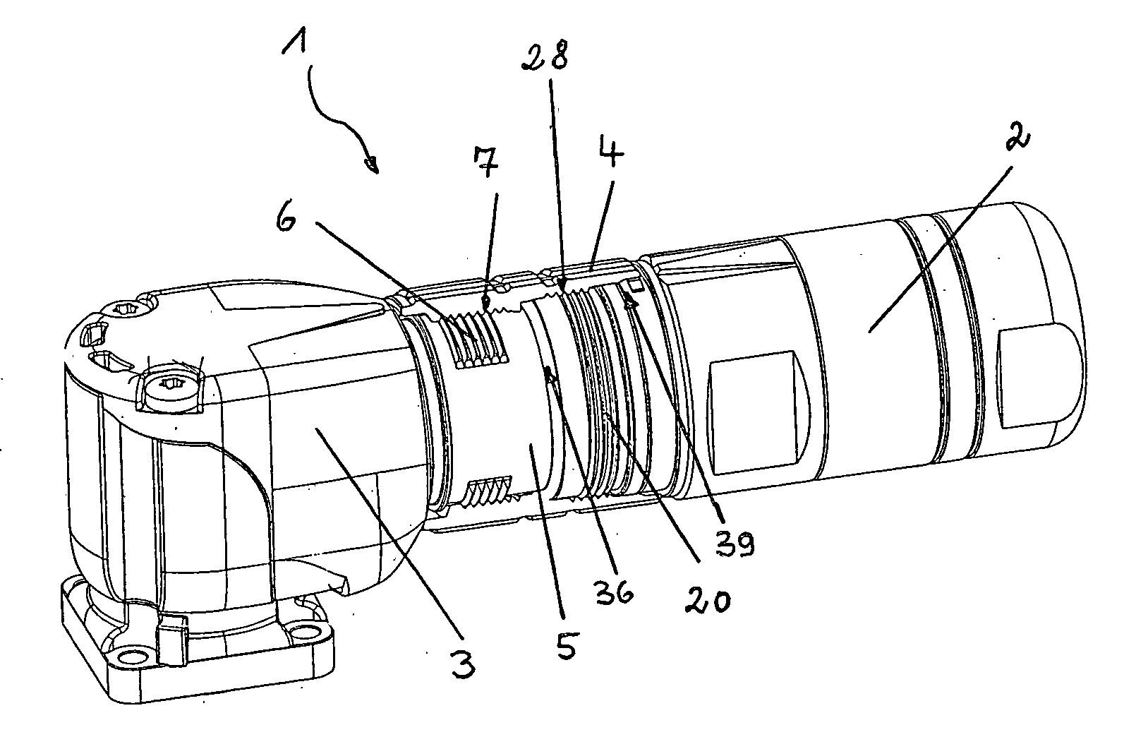
[0011] In order to screw the plug-in connection, the external threads of the plug part and the mating plug part, which correspond to the internal threads of the union nut, are together brought into engagement with the two internal threads of the union nut. When the union nut is rotated, the plug part and the mating plug part are moved simultaneously with respect to one another in the direction of the center of the union nut until the body of the plug part comes into contact with the body of the mating plug part and the electrical connections are produced. In comparison with a union nut with only one internal thread which can be screwed on one side, in this case the number of revolutions required for screwing the plug-in connection is reduced by half, which saves on time. In addition, the front sides of the plug part and the mating plug part are moved twice as far towards one another in comparison with conventional plug-in connectors given a predetermined rotation angle or number of revolutions of the union nut.
[0013] The plug part and the mating plug part advantageously have external threads on their body which are designed to be complementary with respect to the threads of the union nut. It is thus possible for the thread-free region of the internal thread of the union nut, which extends in the plug-in direction, to be inserted virtually completely into the external thread, having a complementary design, of the associated plug part or mating plug part and the screw-tightening is reduced to a rotation of the union nut by at most the thread-free region. One further
advantage is the fact that the plug part and the mating plug part can be plugged together and the
electrical connection produced without the plug-in connection needing to be screwed. This may be useful, for example, when bringing electrical appliances and systems into operation and during faultfinding processes on said electrical appliances and systems if, in the event of a fault, the plug-in connection needs to be detached quickly and a faulty part replaced. After successful testing or after
elimination of faults, the plug part and the mating plug part are connected to one another quickly, safely and permanently by rotating the union nut.
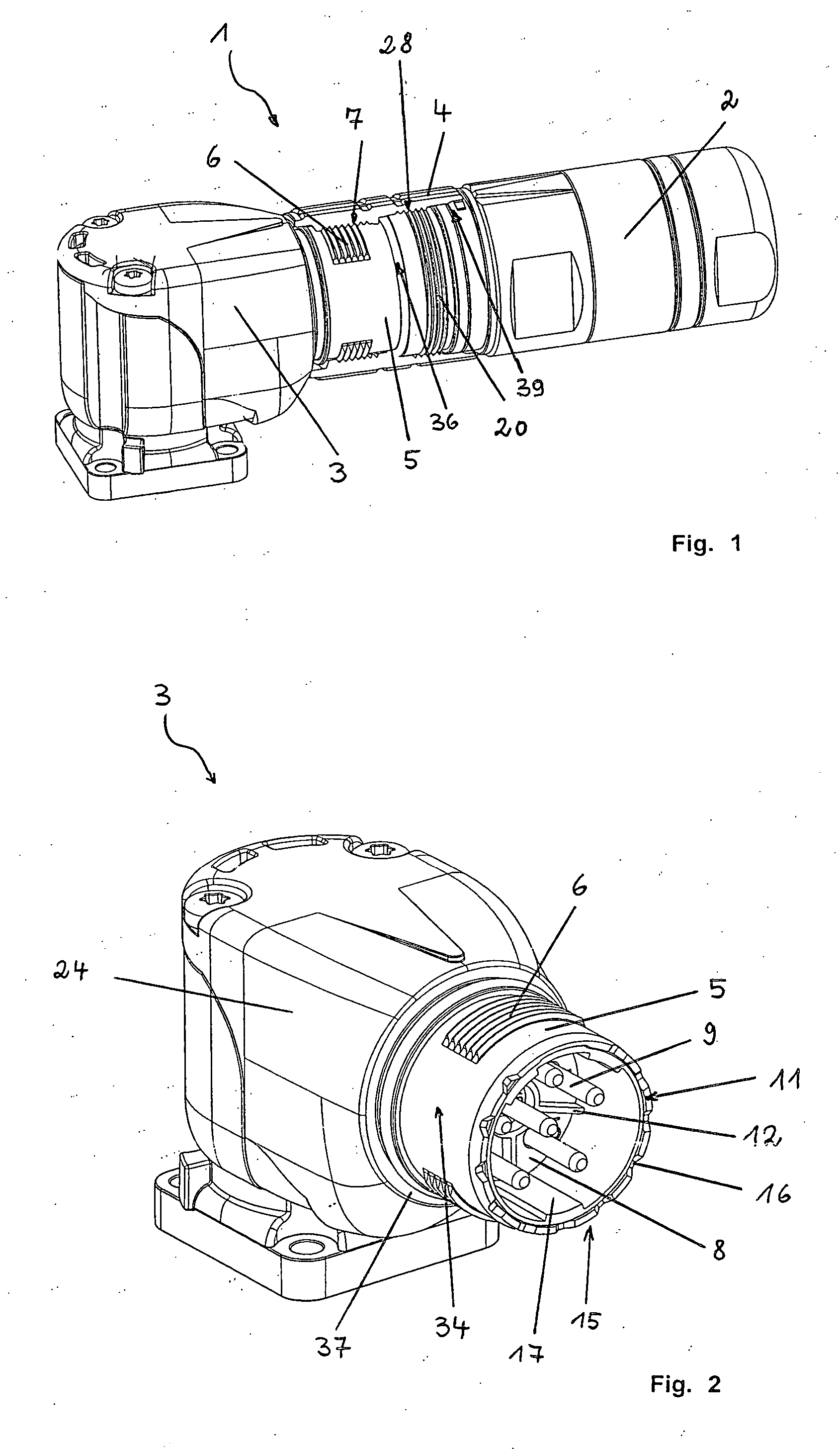
[0014] In one preferred embodiment, the union nut is fixed on the body of the bearing plug part or mating plug part such that it can be rotated and displaced. The union nut is therefore secured against being lost, on the one hand, and, on the other hand, it is possible to insert it into a thread-free region of the thread of the bearing plug-in connector part, which has an advantageous effect on the fitting time when producing the plug-in connection. If both the two internal threads of the union nut and the corresponding external threads of the plug part and the mating plug part are of segmented design, the
electrical connection between the plug part and the mating plug part can be produced in a particularly simple and rapid manner, and the plug part can be locked to the mating plug part. For locking purposes, the union nut only needs to be rotated through approximately one quarter to one half of a revolution for the thread turns of the thread to engage in one another and produce a screw connection.
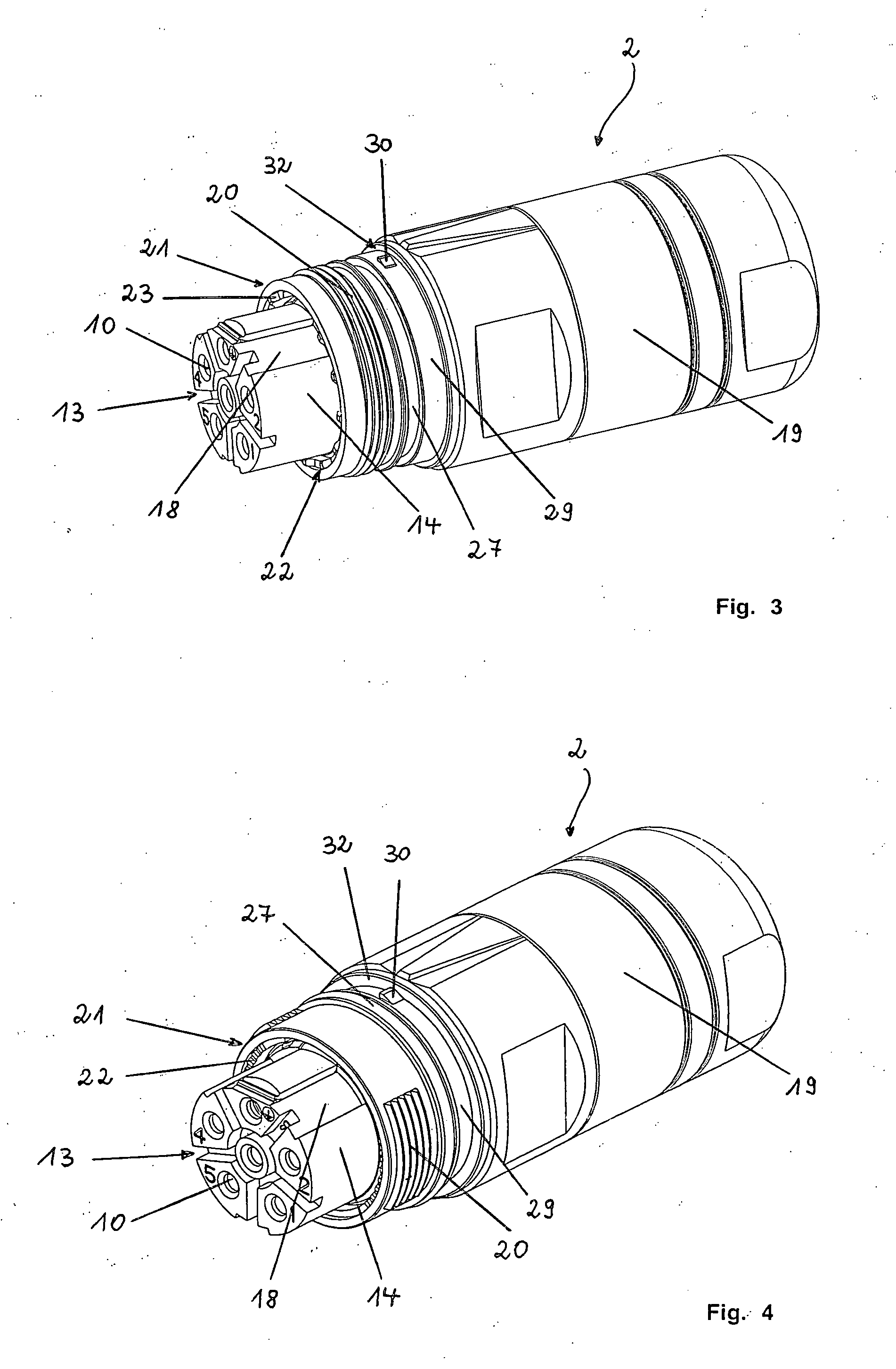
[0015] One development of the invention provides for the plug part and the mating plug part to have, at their front sides, at least partially axially aligned toothed profiles. The toothed profiles are of complementary design and engage one inside the other when the plug-in connection is screwed; in the process they align the plug part and the mating plug part in the circumferential direction of the plug-in connection with respect to one another, without play. The profile sections may be formed on corresponding front faces or outer faces of the plug-in connection parts and have, for example, a sawtooth-shaped, trapezoidal or sinuous cross section. The toothed profiles connect the plug part and the mating plug part to one another in an
interlocking and force-fitting manner, as a result of which any unintentional rotation of the plug part and the mating plug part with respect to one another is prevented when the union nut is tightened, and the electrical contact elements are protected against being damaged.

