Periphery Monitoring Device for Crawler-Type Working Machine

a monitoring device and crawler-type technology, applied in scene recognition, television systems, instruments, etc., can solve problems such as the likely collision of the outer end

Active Publication Date: 2017-03-30
KOMATSU LTD
View PDF1 Cites 10 Cited by
  • Summary
  • Abstract
  • Description
  • Claims
  • Application Information

AI Technical Summary

Benefits of technology

[0024]With the above arrangement, since the images (overview image and single-camera image) taken by the camera and on which the outer-edge guide image is superimposed can be displayed in a remote control seat, a control room or a mobile terminal, a remote-control operator and a third person (e.g., a supervisor) other than the operator of the crawler-type work machine can easily check the overview image and the like. Accordingly, the remote-control operator and the third person can understand the distance from the obstacle to further reliably avoid collision with the obstacle.

Problems solved by technology

Accordingly, even when an operator recognizes an obstacle existing near the hydraulic excavator and a positional relationship between the obstacle and the guideline (e.g., the trajectory drawn by the rear end of the counterweight) through the overview image and the like, when the operator conducts the ultra pivot turn, the outer end of each of the crawlers is positioned outside the guideline to cause the operator to erroneously recognize a distance between the outer end and the obstacle, so that the outer end is likely to collide with the obstacle and the like.

Method used


Image

  • Periphery Monitoring Device for Crawler-Type Working Machine
  • Periphery Monitoring Device for Crawler-Type Working Machine
  • Periphery Monitoring Device for Crawler-Type Working Machine

Examples


first exemplary embodiment

(1) Overall Arrangement

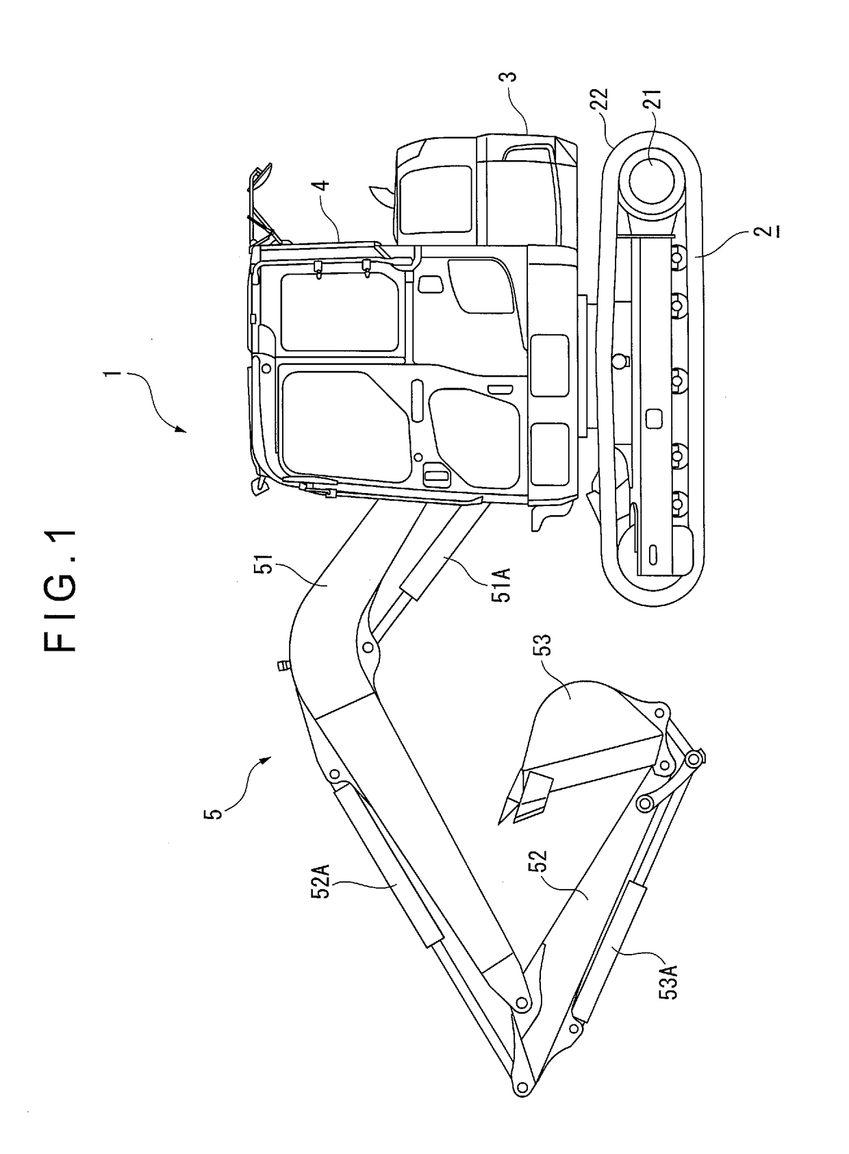
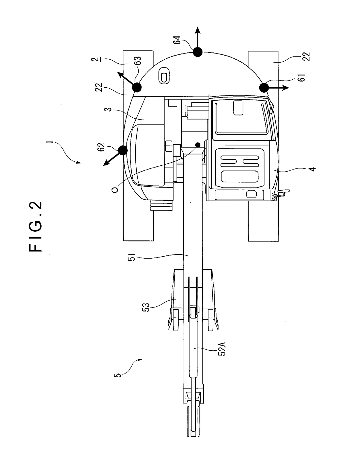
[0040]As shown in FIGS. 1 and 2, a hydraulic excavator 1 in a form of a crawler-type work machine includes an undercarriage 2, an upper revolving body 3, a cab (operation room) 4, and working equipment 5. The undercarriage 2 is provided in a form of a crawler-type undercarriage and includes: a truck frame (not shown) beneath the upper revolving body 3; and a pair of traveling devices 21 respectively provided on both ends of the truck frame in a vehicle width direction orthogonal to a travel direction. Each of the traveling devices 21 includes crawlers 22 each wound around a drive wheel and an idler wheel projecting from the truck frame. When the drive wheels (first and second drive wheels) are driven, the hydraulic excavator 1 is moved forward and backward in an extension direction of the crawlers 22.

[0041]The right and left traveling devices 21 can independently drive the respective drive wheels (to move the hydraulic excavator 1 forward and backward). When t...

second exemplary embodiment

[0066]In a second exemplary embodiment, a hydraulic excavator 1A including a blade for ground leveling, the blade being attached to a front side of the undercarriage, will be described below.

[0067]The hydraulic excavator 1A shown in FIGS. 10 and 11 is the same as the hydraulic excavator 1 shown in FIGS. 1 and 2 except for the blade 23 attached to the front side of the undercarriage 2. Accordingly, the description of the components other than the blade 23 will be omitted. The blade 23 may be detachable. The blade 23 includes a plurality of hydraulic cylinders (not shown) and is movable vertically and horizontally using the hydraulic cylinders. It should be noted that the blade 23 is regarded as a part of the undercarriage 2 since the blade 23 is attached to the undercarriage 2.

[0068]In the second exemplary embodiment, a drawing method of the guideline by the guideline changer 71 will be described. FIG. 12 is a simplified plan view showing the hydraulic excavator 1A provided with the ...


PUM


Abstract

A surroundings monitoring device of a crawler-type work machine includes: cameras configured to take images of surroundings of the crawler-type work machine; a display unit configured to display the images taken by the cameras; and a controller configured to superimpose an outer-edge guide image generated based on the farthest position of an undercarriage from a revolution center of the crawler-type work machine on the display unit.

Description

TECHNICAL FIELD[0001]The present invention relates to a surroundings monitoring device of a crawler-type work machine.BACKGROUND ART[0002]A surroundings monitoring controller of a work machine has been typically known in order for an operator to revolve an upper revolving body while checking surrounding conditions of the upper revolving body using a monitor provided inside a cab, the monitor displaying an overview image generated from images taken by a plurality of cameras attached to a vehicle body of the work machine (see, for instance, Patent Literature 1).[0003]Such a surroundings monitoring device also has been installed in various hydraulic excavators in recent years.[0004]A hydraulic excavator occasionally includes an optional attachment (e.g., a blade) in addition to working equipment including a boom, arm, and bucket. The blade is attached to an undercarriage and the undercarriage travels with the blade kept in contact with the ground, thereby conducting earth filling and g...

Claims


Application Information

Patent Timeline
Patent Type & Authority Applications(United States)
IPC IPC(8): E02F9/26G06K9/00H04N5/272B60R1/00H04N7/18
CPCE02F9/261B60R1/00H04N7/183B60R2300/80G06K9/00805E02F3/32E02F3/964H04N5/272H04N7/181B60R2300/303B60R2300/306B60R2300/607B60R16/023E02F9/24B60R2300/00B60R2021/0081H04N23/51G06V20/58
Inventor MACHIDA, MASAOMIKURIHARA, TAKESHI
Owner KOMATSU LTD
Why Eureka
Try Eureka