
Curved surgical tool driver

a technology of surgical tool driver and curved tip, which is applied in the field of surgical instruments, can solve the problems of long rehabilitation period, significant trauma to patients, and inconvenient use, and achieve the effect of convenient proper tool placemen

Inactive Publication Date: 2008-02-05
SYMMETRY MEDICAL MFG INC
View PDF25 Cites 48 Cited by
  • Summary
  • Abstract
  • Description
  • Claims
  • Application Information

AI Technical Summary

Benefits of technology

[0013]An advantage of the present invention is providing a surgical tool driver suitable for use in minimally invasive surgical procedures.
[0014]Another advantage is of the present invention is providing a surgical tool driver that facilitates proper tool placement even with anatomical structures present between an incision through which the tool is inserted and the site at which the tool is targeted.
[0015]Yet another advantage is providing a surgical tool driver for minimally invasive surgical procedures that can be adapted for use with different types of driving sources and for different types of surgical tools.

Problems solved by technology

Even with a successful surgery, the trauma to the patient is significant from open surgical procedures.
As a result, rehabilitation periods are long and require dedication from the patient over an extended difficult time period to ensure the best possible result.
Even with a skilled surgeon and a patient committed to a rehabilitation program, it is not always possible to achieve the desired results due in part to the surgical damage to areas surrounding the joint and the extensive scaring that can result.
However, procedures for some other joints, such as hips, are not as easily adapted to minimally invasive surgical procedures.
Because of surrounding hard and soft tissue structures, it is difficult to position properly inline surgical tools through incisions spaced about the joint.
Because of obscuring anatomical features, it is difficult to use known acetabular reamers during a minimal invasive hip arthroplasty.
As a consequence, many common hip procedures, such as total hip replacements, are routinely performed through large incisions, in open procedures, exposing the entire joint, with the increased trauma caused thereby perceived as a necessary disadvantage.

Method used


Image

  • Curved surgical tool driver
  • Curved surgical tool driver
  • Curved surgical tool driver

Examples


Embodiment Construction

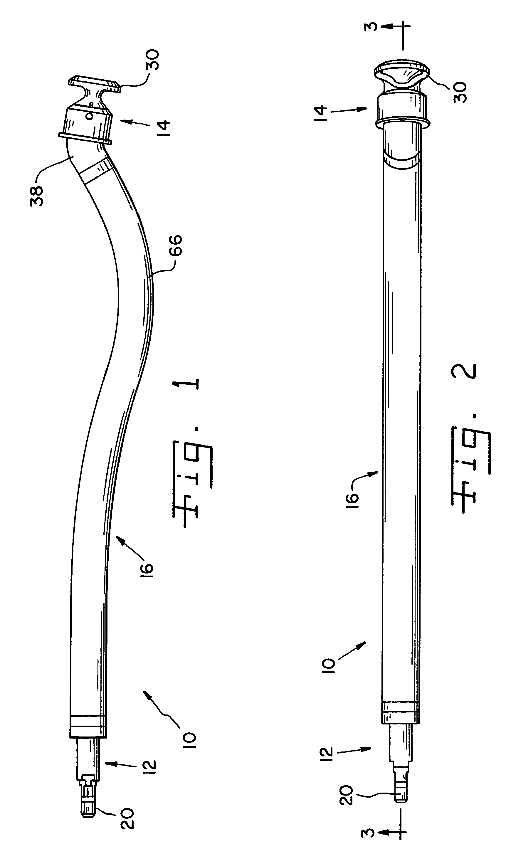
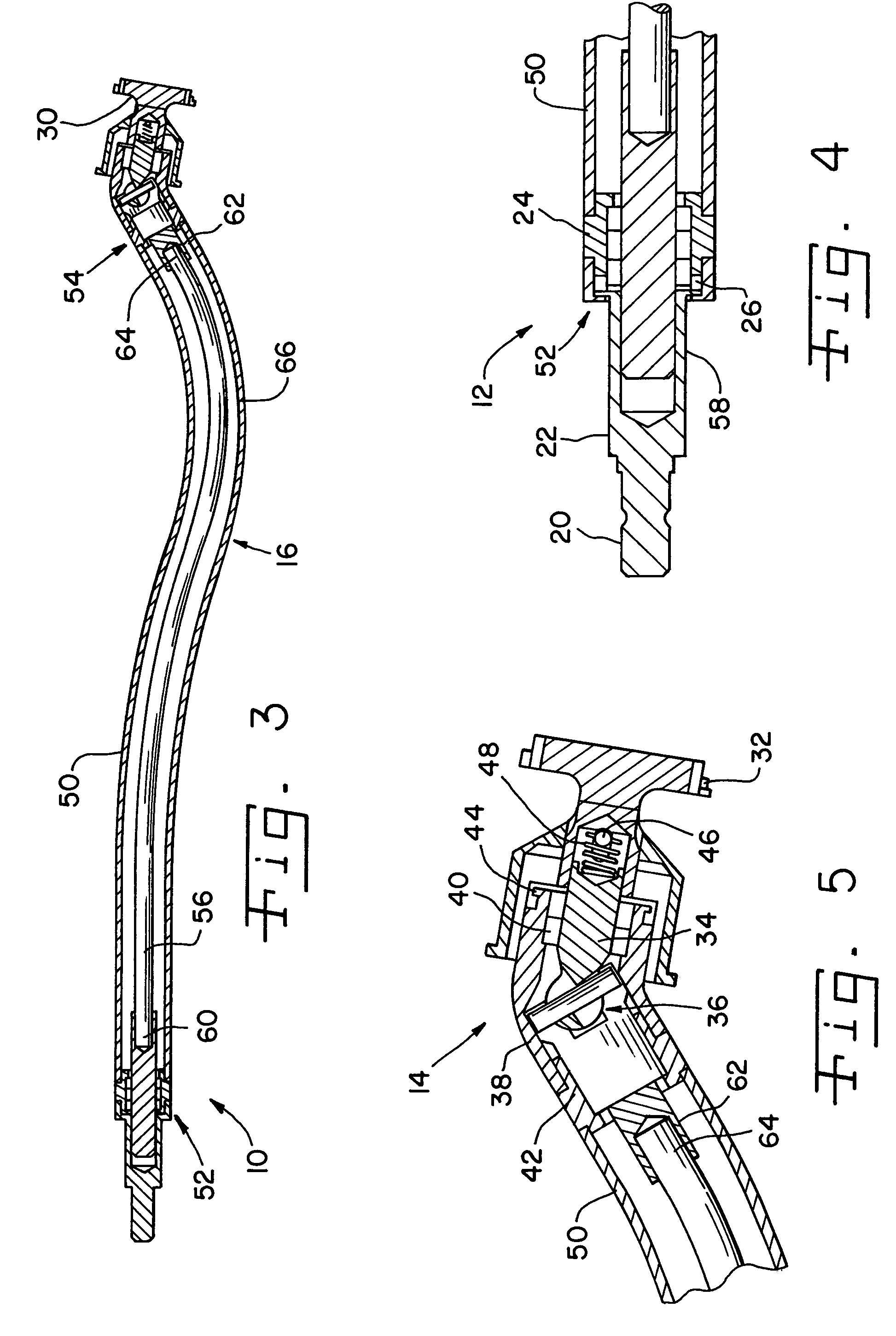
[0023]Referring now to the drawings, and more particularly to FIG. 1, there is shown a medical instrument in the nature of a surgical tool driver 10 of the present invention. Driver 10 is particularly suited for use in minimally invasive surgical procedures, such as total hip arthroplasty performed through small surgical incisions. Driver 10 generally includes a driven end attachment assembly 12, a driving end attachment assembly 14, and a shaft assembly 16 extending generally between driven end attachment assembly 12 and driving end attachment assembly 14.

[0024]Driven end attachment assembly 12 includes a drive coupling 20, by which tool driver 10 is coupled to a rotary drive source. Coupling 20 is an exposed portion of a short shaft 22 retained in a sleeve 24 connected to shaft assembly 16. A bearing or bearings 26 allow shaft 22 to rotate relative to sleeve 24. It should be understood that coupling 20 may be provided in a variety of different shapes, configurations, sizes and for...


PUM


Abstract

A surgical tool driver has a driven end connectable to a rotary drive source and a driving end connectable to a surgical tool. A shaft assembly there between includes a hollow outer shaft and a flexible drive shaft for transmitting rotary power from the driven end to the driving end. The shaft assemble is curved for bypassing anatomical features in a patient.

Description

BACKGROUND OF THE INVENTION[0001]1. Field of the Invention[0002]The present invention pertains generally to surgical instruments and, more particularly, to surgical instruments such as surgical tool drivers particularly suited for use in minimal invasive surgical procedures.[0003]2. Description of the Related Art[0004]Early techniques for performing major orthopedic surgical procedures, such as joint replacements or reconstructions, included making large incisions and exposing the entire joint. Even with a successful surgery, the trauma to the patient is significant from open surgical procedures. As a result, rehabilitation periods are long and require dedication from the patient over an extended difficult time period to ensure the best possible result. Even with a skilled surgeon and a patient committed to a rehabilitation program, it is not always possible to achieve the desired results due in part to the surgical damage to areas surrounding the joint and the extensive scaring tha...

Claims


Application Information

Patent Timeline
Patent Type & Authority Patents(United States)
IPC IPC(8): A61B17/00A61B17/58A61B17/16
CPCA61B17/1624A61B17/1631A61B17/1666
Inventor MYERS, REESE K.SALYER, PAUL E.MENDENHALL, BRIAN C.
Owner SYMMETRY MEDICAL MFG INC
Learn More