Bicompartmental implants and method of use

a technology of bicompartmental implants and implants, which is applied in the direction of prosthesis, femoral head, endoscopic cutting instruments, etc., can solve the problems of affecting the kinematics of individual patients, affecting the kinematics of the individual patient, and affecting the kinematics of the joint, so as to achieve minimally invasive surgical procedures, and reduce the risk of infection

Inactive Publication Date: 2009-04-21
CAYENNE MEDICAL INC
View PDF266 Cites 89 Cited by
  • Summary
  • Abstract
  • Description
  • Claims
  • Application Information

AI Technical Summary

Benefits of technology

[0025]The present invention provides an implant system that restores individual patient joint kinematics and involves minimally invasive surgical procedures. The instruments and implants disclosed accomplish accurate bone and soft tissue preparation, implant orientation and implant fixation through limited surgical exposure. The implant system is comprised of implants and instrumentation that provide intraoperative surgical options for articular constraint and facilitate proper alignment and orientation of the knee to restore kinematics as defined by the individual patient anatomy. To do so, the implants provide a surgeon intraoperative options to reconstruct various degrees of joint stability via selection of fixed or mobile bearing components for each compartment of the knee (medial tibiofemoral joint, lateral tibiofemoral joint and patellofemoral joint). The range of implants may cover each compartment of the knee and may include combinations of fixed and mobile bearing configurations.
[0027]Proper alignment and positioning of the implant components is facilitated by instrumentation that utilizes the soft tissue structures of the knee to guide bony resections for patient-specific alignment and orientation of the implants. The surgical instrumentation prepares the articular surfaces of a synovial joint from a single point of reference to allow the introduction of separate components for the medial and lateral tibiofemoral compartments, and the patellofemoral compartments with precise orientation. Thus, the instrumentation provides bony resections in accordance with such alignment and orientation requirements. The alignment positioning is important for proper restoration of anatomic alignment of the knee joint and for proper orientation of the components to one another.
[0028]With respect to forming or sculpting articular surfaces of a joint, the method of the current invention enables the articular bone surfaces to be sculpted according to the individual physiology of each patient to restore as much as possible the natural function of the joint. In this method, a bone sculpting tool is attached to one of the bones of a joint, and the tool sculpts the articular surface of the other bone as the joint is articulated.

Problems solved by technology

The articular surfaces are subject to a variety of diseases, accidents and the like that cause the surfaces to be damaged.
Degenerative arthritis causes progressive pain, swelling, and stiffness of the joints.
Changes in the articular surfaces resulting from arthritis decrease stability and increase the translation of the joint.
While drug therapies may temporarily provide relief of pain, progression of the disease, with resulting deformity and reduced function, ultimately necessitates surgery.
Current methods of preparing the intraarticular rigid elements of a joint to receive components as in joint replacement surgery involve an extensive surgical exposure.
While implant systems have been developed with fixed bearing elements or mobile bearing elements on the medial and lateral sides of the tibiofemoral joint, systems have not been developed having a combination of a fixed bearing on one side and a mobile bearing on the other side of the tibiofemoral joint.
The resultant lower contact stress reduces the possibility of damage sometimes encountered with some fixed bearing designs wherein the yield strength of the bearing material is exceeded.
In general, fixed bearing implant designs are less difficult to properly align and balance than mobile bearing designs.
However, with mobile bearing designs, there is the possibility of the bearing becoming dislodged from the implant.
Additionally, mobile bearing knee designs are more surgically demanding to implant then fixed bearing designs.
Two primary difficulties exist with current joint replacement surgeries.
A difficulty with implanting both modular and non-modular knee implants having either separate femoral and / or tibial components has been achieving a correct relationship between the components.
Surgical instruments available to date have not provided trouble free use in implanting multi-part implants wherein the femur and tibia are prepared for precise component-to-component orientation.
While alignment guides aid in accurate orientation of the components relative to the axis of the long bones to achieve a restoration of a correct tibiofemoral alignment (usually 4-7degrees valgus), they provide limited positioning or guidance relevant to correct component-to-component alignment and / or ligament tension to restore alignment.
Complications may result if the implant is not correctly oriented with respect to the supporting bone.
If the implant is not placed normal to the mechanical axis, a shearing force results between the implant and bone that may lead to implant loosening.
If the implants are malaligned, the resulting mechanical axis may be shifted medially or laterally, resulting in an imbalance in the loads carried by the medial or lateral condyles.
This imbalance, if severe, may lead to early failure of the implant.
In addition, the orientation of the components to each other, for example the orientation of the femoral to the tibial component, with unicondylar and bicondylar implants has largely not been addressed.
This may account for the high failure rates of early bicondylar designs and as well as for the higher failure rate of unicondylar implants relative to total knee implants as demonstrated in some clinical studies.
While efforts are made to tailor the prosthesis to the needs of each patient by suitable prosthesis choice and size, this in fact is problematical inasmuch as the joint physiology of patients can vary substantially from one patient to another.
Although arthroscopic procedures are far less invasive and are often successful for minor surgical repairs, (as when an articular surface is to be smoothed, for example, or cartilage is to be repaired), such procedures generally are not appropriate for substantial joint replacement.
They are generally inadequate for replacing joint surfaces with artificial implants.

Method used


Image

  • Bicompartmental implants and method of use
  • Bicompartmental implants and method of use
  • Bicompartmental implants and method of use

Examples


Embodiment Construction

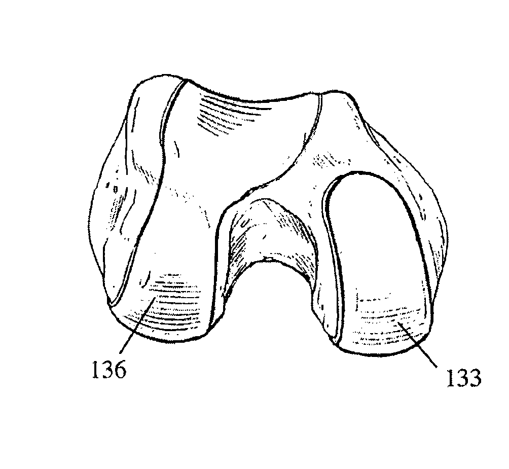
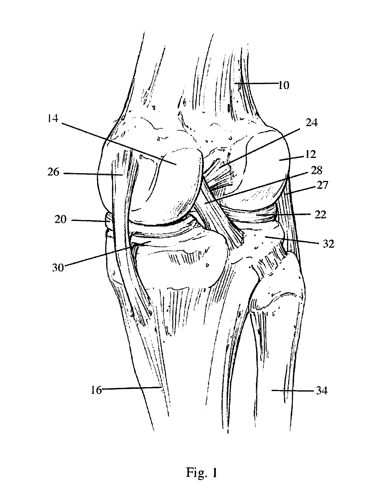
[0079]FIG. 1 illustrates the general anatomy of the knee joint. The femur 10 has the lateral femoral condyle 12 and the medial femoral condyle 14 on its knee-joint articulating surface. The tibia 16 has the lateral meniscus 22 (generally opposite the lateral femoral condyle 12) and the medial meniscus 20 (generally opposite the medial femoral condyle 14) on its knee-joint articulating surface. The anterior cruciate ligament 24, the posterior cruciate ligament 28, the medial collateral ligament 26 and the lateral collateral ligament 27. The medial tibial condyle 30 and the lateral tibial condyle 32 support the menisci 20 and 22, which in turn support the femur 10. Additionally, the fibula 34 engages the tibia 16.

[0080]Typically, a total knee joint replacement involves replacing the articular surfaces of the lateral femoral condyle 12, the medial femoral condyle 14, the medial tibial condyle 30 and the lateral tibial condyle 32. The lateral meniscus 22, and the medical meniscus 20 are...


PUM

PropertyMeasurementUnit
lengthaaaaaaaaaa
thicknessaaaaaaaaaa
sizesaaaaaaaaaa

Abstract

The present invention provides a method and device for restoring individual patient joint kinematics using minimally invasive surgical procedures. The instrumentation of the invention sculpts the articular surface of a first bone that normally articulates in a predetermined manner with a second bone. The instrumentation includes a bone sculpting tool and a mount for attaching the tool to the second bone. The implant system is comprised of implants that provide intraoperative surgical options for articular constraint and facilitate proper alignment and orientation of the joint to restore kinematics as defined by the individual patient anatomy.

Description

CROSS REFERENCE TO RELATED APPLICATIONS[0001]This application is a continuation of U.S. patent application Ser. No. 10 / 159,147, filed May 29, 2002, which is a divisional application of U.S. patent application Ser. No. 09 / 882,591, filed Jun. 14, 2001, now issued as U.S. Pat. No. 6,482,209, the entireties of which are hereby incorporated by reference.BACKGROUND OF THE INVENTION[0002]A joint generally consists of two relatively rigid bony structures that maintain a relationship with each other. Soft tissue structures spanning the bony structures hold the bony structures together and aid in defining the motion of one bony structure to the other. In the knee, for example, the bony structures are the tibia and the femur. Soft tissue such as ligaments, tendons, menisci, and capsule provide support to the tibia and femur. A smooth and resilient surface consisting of articular cartilage covers the bony structures. The articular surfaces of the bony structures work in concert with the soft ti...

Claims


Application Information

Patent Timeline
Patent Type & Authority Patents(United States)
IPC IPC(8): A61F2/38A61B17/00A61B17/02A61B17/16A61B17/32A61B17/56A61F2/00A61F2/30A61F2/34A61F2/36A61F2/46
CPCA61B17/025A61B17/1628A61B17/1631A61B17/1666A61B17/1675A61B17/32002A61F2/30724A61F2/38A61F2/4684A61F2/461A61B17/00234A61B17/0206A61B2017/00398A61B2017/00539A61B2017/00557A61B2017/0268A61B2017/0275A61B2017/1602A61F2/30767A61F2/30942A61F2/34A61F2/3662A61F2/3859A61F2/3872A61F2/3877A61F2/389A61F2002/30092A61F2002/30616A61F2002/30884A61F2002/30894A61F2002/3668A61F2002/3895A61F2002/4623A61F2002/4631A61F2002/4635A61F2002/4681A61F2002/4693A61F2002/4694A61F2210/0014A61F2310/00017A61F2310/00023A61F2310/00029A61F2310/00952A61F2002/30604A61F2/4603
Inventor ENGH, GERARD A.JOHNSON, WESLEY D.
Owner CAYENNE MEDICAL INC
Why Eureka
Try Eureka