Device for the repair of arteries

Inactive Publication Date: 2008-02-05
ANSON MEDICAL LTD
View PDF64 Cites 221 Cited by
  • Summary
  • Abstract
  • Description
  • Claims
  • Application Information

AI Technical Summary

Benefits of technology

[0022]The connection between the wires can include a sleeve which supplies strength, radio-op

Problems solved by technology

This reduces the possibility of the device's pulling out from its implantation site.
If they do not, then the device may not pass fully through the structures or the device may remove a core of material (due

Method used


Image

  • Device for the repair of arteries
  • Device for the repair of arteries
  • Device for the repair of arteries

Examples


Embodiment Construction

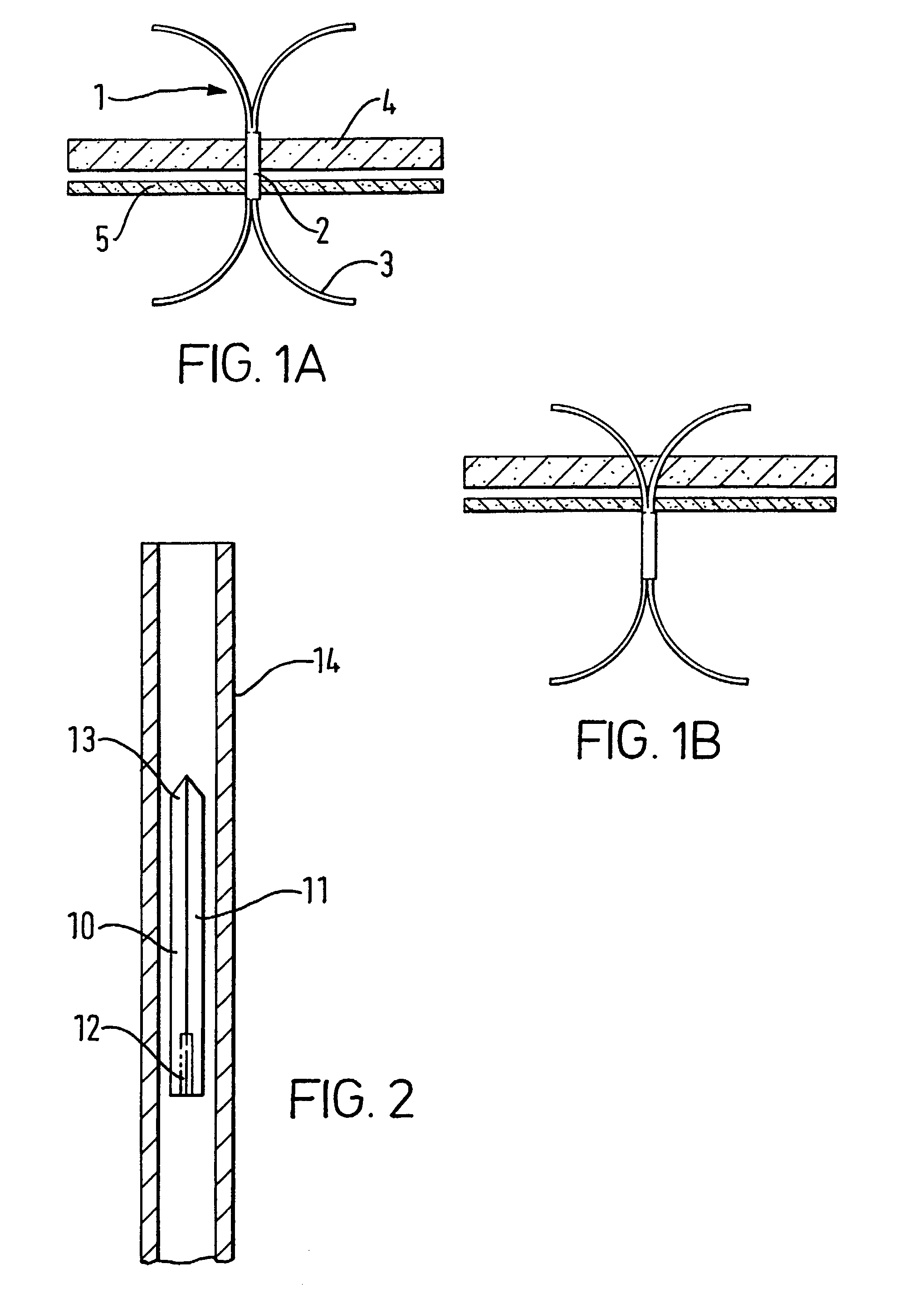
[0032]Turning to the drawings, FIG. 1 shows a prior art fixator 1 (as disclosed in WO 00 / 07506) having a central section 2 and four legs 3. In FIG. 1A, fixator 1 is correctly positioned across artery wall 4 and graft wall 5, with central section 2 being implanted in artery wall 4. This position arises from the leading legs 3 having passed through graft wall 5 and artery wall 4 together, only separating after they have emerged from artery wall 4.

[0033]FIG. 1B shows the incorrect placement of fixator 1 resulting from paired legs 3 separating while passing through artery wall 4. It can be seen that, if fixator 1 is advanced any further, a core of material from graft wall 5 and then artery wall 4 will be removed by fixator 1.

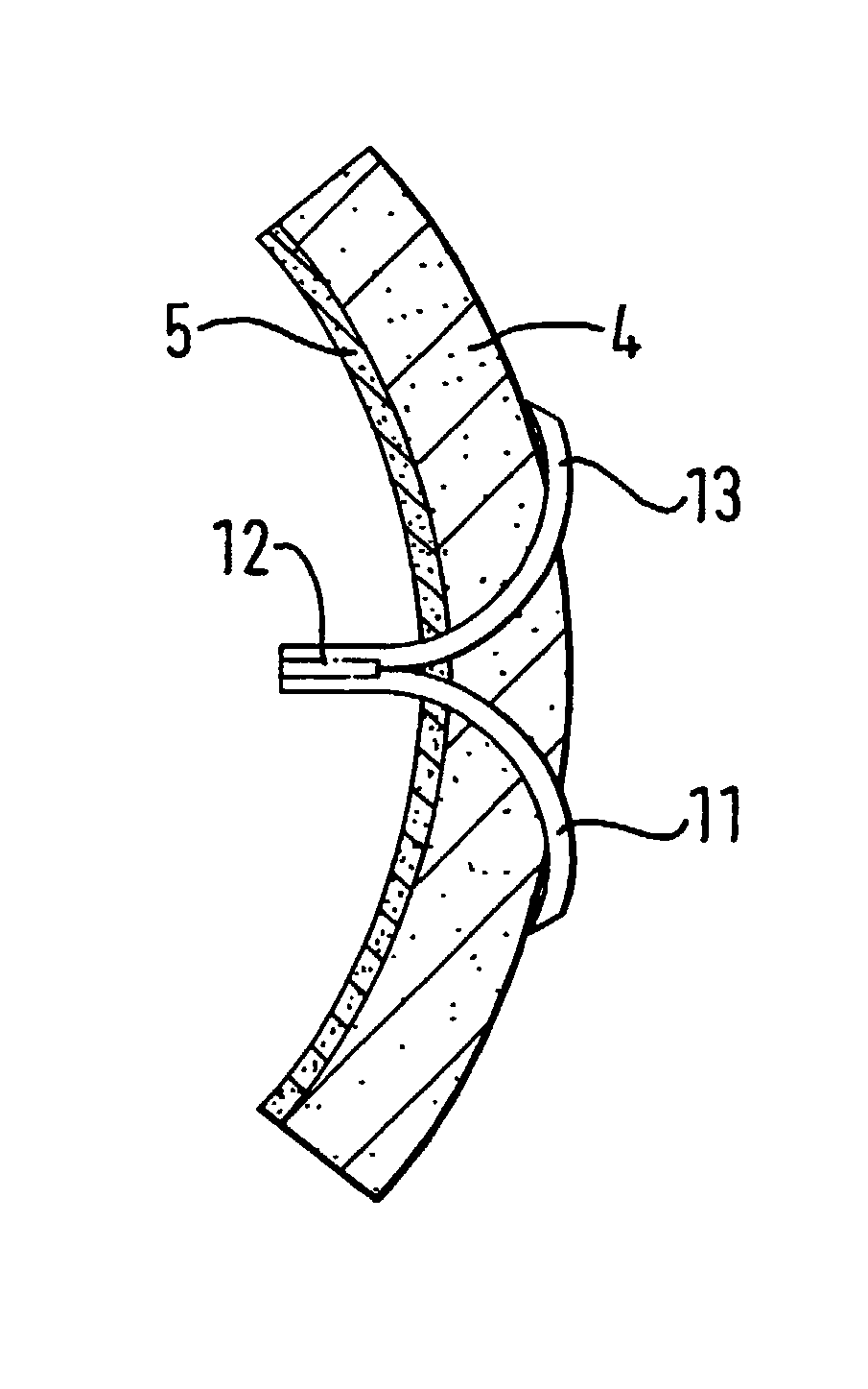
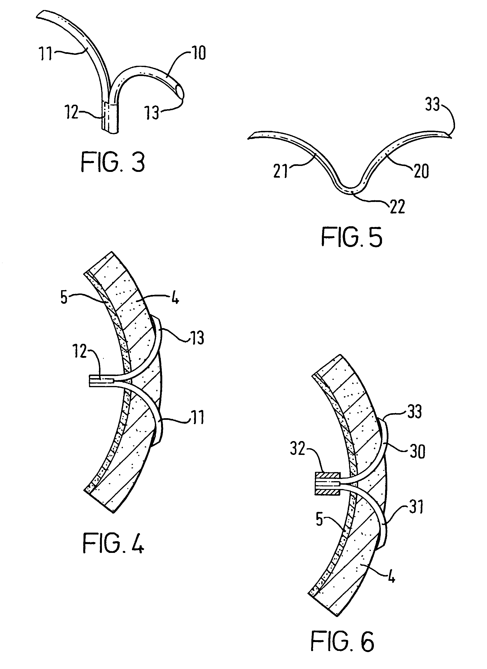
[0034]FIGS. 2 to 4 show an embodiment of the present invention, in which fixator 10 has two legs 11 which are welded together at boss 12 and which terminate at sharpened ends 13. Legs 11 are resiliently biased into the splayed configuration shown in FIG. 3, but can ...


PUM


Abstract

A device is provided for piercing a graft and artery wall in order to retain the graft on the artery. The device has a central section with an abutment surface for contacting the inner wall of the graft and two elongate members with distal ends for contacting the outer wall of the artery when the device is pierced through the graft and artery. The elongate members are biased so as to urge the abutment surface into the graft and retain the graft on the artery.

Description

[0001]This application is the U.S. National Stage entry under 35 U.S.C. § 371 of PCT / GB01 / 00551, filed Feb. 9, 2001.FIELD OF THE INVENTION[0002]The present application relates to a device for retaining a graft on an artery, and in particular to a device which can be used surgically to join living tissue or to attach graft material to living tissue. More specifically, it can be used to join a vascular graft to an artery wall, preferably by minimally invasive or endolumenal means.BACKGROUND OF THE INVENTION[0003]WO 92 / 05828 discloses a wire-form suture which comprises an open wire ring, the ends of which have been arranged to overlap. The wire-formed ring can be fully or partially straightened, one end sharpened and the whole device driven through adjoining tissues. The wire has a spring or shape memory characteristic which causes it to re-form into a ring shape when in place thereby drawing together the tissues.[0004]An improvement to this design is disclosed in WO 00 / 07506 (in the n...

Claims


Application Information

Patent Timeline
IPC IPC(8): A61B17/08A61F2/06A61B17/00A61B17/064
CPCA61B17/064A61B2017/00867A61F2/064A61B2017/0645
Inventor PHILLIPS, PETERKEEBLE, DUNCAN
Owner ANSON MEDICAL LTD
Why Eureka
Try Eureka