H2S scavenging method

a scavenging method and h2s technology, applied in the field of h2s scavenging method, can solve the problems of affecting human, animal and plant life, affecting the economic feasibility of conventional amine sweetening, and the droplets produced by this mechanical method of atomization are generally larger than 15 microns in diameter

Active Publication Date: 2008-02-05
GAS TECH INST
View PDF3 Cites 1 Cited by
  • Summary
  • Abstract
  • Description
  • Claims
  • Application Information

AI Technical Summary

Benefits of technology

[0010]Accordingly, it is one object of this invention to provide a method for H2S removal from H2S-containing gaseous streams which reduces the amount of H2S scavenging agent required compared to conventional methods.
[0011]It is another object of this invention to provide a method for H2S removal from H2S-containing gaseous streams which reduces the length of contactor pipe required compared to conventional methods.
[0012]These and other objects of this invention are addressed by a method for removing H2S from H2S-containing gaseous streams comprising the steps of introducing an H2S-containing gaseous stream into a flow channel, introducing at least one liquid chemical H2S scavenging agent into the flow channel, transforming said at least one liquid chemical H2S scavenging agent directly within the flow channel into a plurality of H2S scavenging agent droplets, and contacting the plurality of H2S scavenging agent droplets with the H2S-containing gaseous stream, whereby at least a portion of the H2S is absorbed by the plurality of H2S scavenging agent droplets. The method of this invention creates order-of-magnitude increases in interfacial area available for mass transfer over conventional methods, which, in turn allows less chemical and / or less length and weight of contactor piping to be used compared to conventional direct injection methods and systems for removal of H2S from H2S-containing gaseous streams.
[0014]In accordance with another embodiment of the method of this invention, transformation of the liquid chemical H2S scavenging agent into droplets is accomplished by introducing the H2S-containing gaseous stream into a flow channel containing at least one contactor element having at least one vibratile surface, vibrating the at least one vibratile surface at an ultrasonic frequency, resulting in at least one vibrating surface, and contacting the at least one vibrating surface with at least one liquid chemical H2S scavenging agent, forming a plurality of liquid chemical H2S scavenging agent droplets within the flow channel. The droplets thus formed contact the H2S-containing gaseous stream, whereby at least a portion of the H2S in the H2S-containing gaseous stream is absorbed by the liquid chemical H2S scavenging agent droplets and the concentration of the H2S in the H2S-containing gaseous stream is reduced.

Problems solved by technology

In addition to the corrosive and other adverse effects that such impurities have upon equipment and processes with which such gaseous streams interact, noxious emissions are commonly produced from combustion of the natural gas as a result of oxidation of the hydrogen sulfide.
The resulting sulphur oxides are a major contributor to air pollution and may have detrimental impact upon humans, animals, and plant life.
For this gas segment, conventional amine sweetening is not economically feasible, particularly when carbon dioxide (CO2) removal is not required.
However, droplets produced by this mechanical method of atomization are generally larger than 15 microns in diameter.
However, studies also have been conducted which show that the performance of direct-injection scavenging systems is more difficult to predict than tower-based systems because the underlying fundamentals of direct injection are largely unknown.
In addition, H2S removal results, chemical usage, and chemical costs are highly site-specific, especially with regard to gaseous fluid velocity, liquid-gas mixing conditions, and contact time.
Several problems with conventional approaches for H2S removal from H2S-containing gaseous streams continue to plague the industry.
These include insufficient removal of H2S, excessive use of scavenging agents, and the requirement for excessive lengths of piping and the associated size / weight of piping contactors.
Such problems are of considerable importance in offshore applications where space is very limited.

Method used


Image

  • H2S scavenging method
  • H2S scavenging method
  • H2S scavenging method

Examples


Embodiment Construction

Definitions

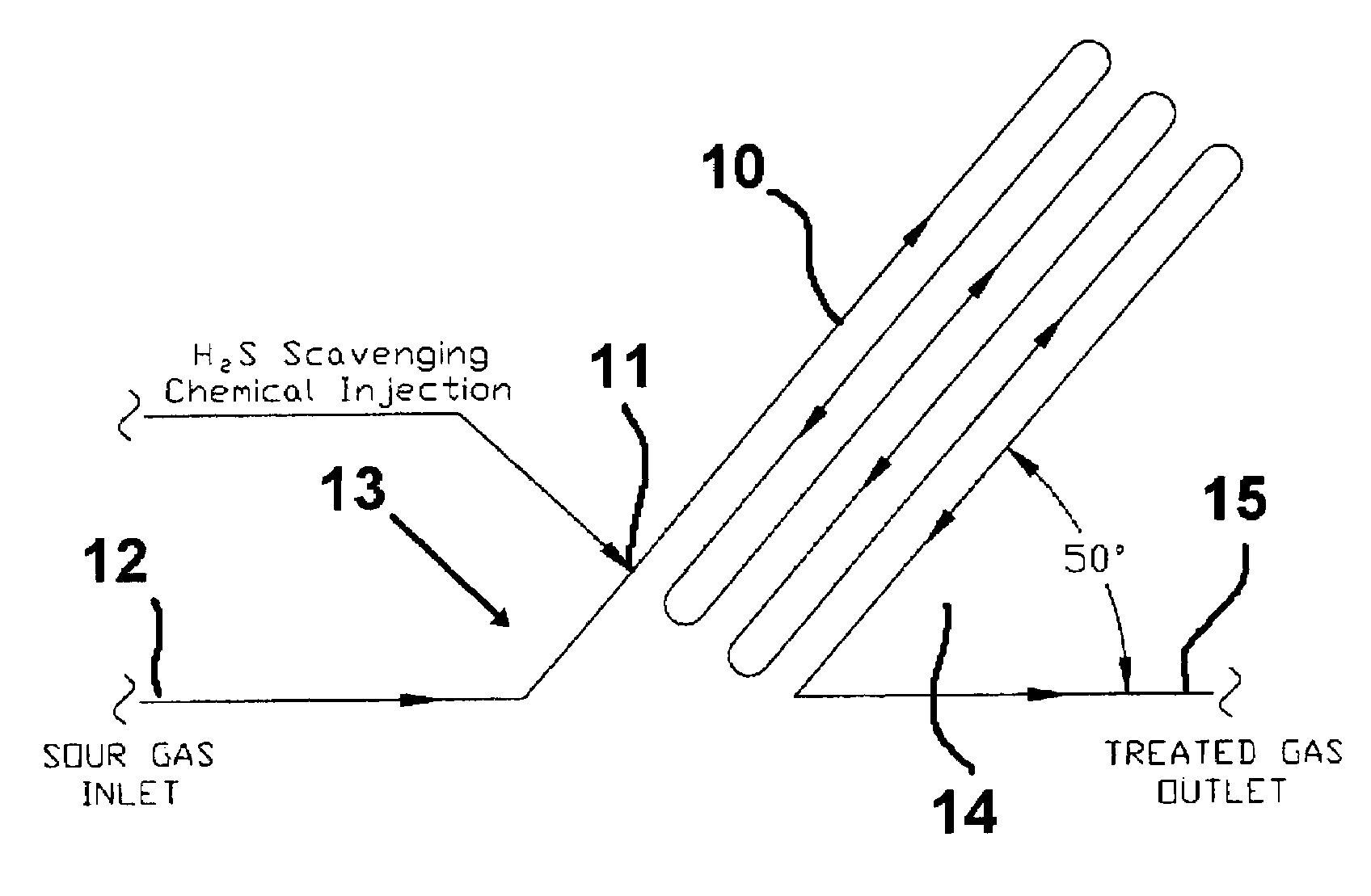
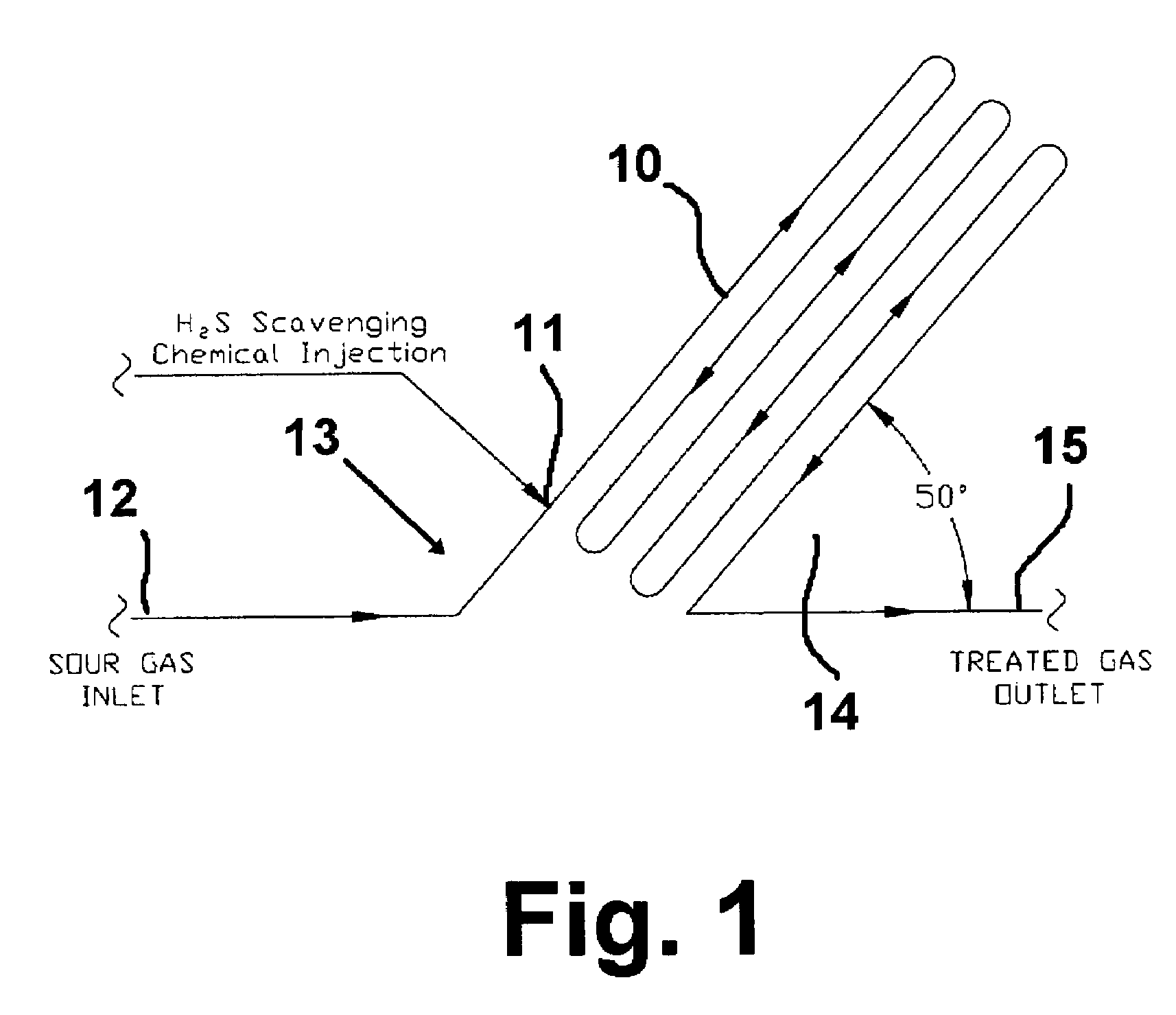
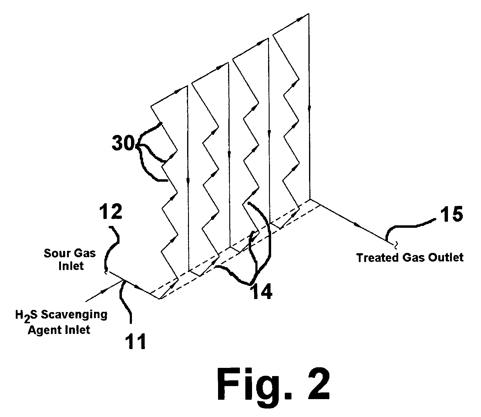
[0021]As used herein, the term “flow channel” refers to any enclosed passage for transport of a fluid. Examples include pipes, tubes and spaced apart planar elements closed off on two opposed sides.

[0022]As used herein, the term “liquid stream” refers to a continuously flowing liquid or uninterrupted flowing liquid in contrast to liquid droplets or liquid droplet streams, which are considered to constitute a non-continuous or interrupted flow of liquid.

[0023]As used herein, the term “ultrasonic frequency” refers to a frequency that is above the audible range, typically considered to be about 20,000 Hz and above.

[0024]In accordance with one embodiment of the method of this invention, an H2S-containing gaseous stream is introduced into the vertically lower end of an inclined flow channel, resulting in an upward flow of the stream, and a liquid stream of an H2S scavenging agent is introduced into the flow channel proximate the vertically lower end of the inclined flow channe...


PUM


Abstract

A method for removing H2S from H2S-containing gaseous streams in which an H2S-containing gaseous stream is introduced into a flow channel and at least one liquid chemical H2S scavenging agent is also introduced into the flow channel. Directly within the flow channel, liquid chemical H2S scavenging agent is transformed into a plurality of H2S scavenging agent droplets, which plurality of H2S scavenging agent droplets are contacted with the H2S-containing gaseous stream, whereby at least a portion of the H2S is absorbed by the plurality of H2S scavenging agent droplets. In accordance with one embodiment, transformation of the liquid chemical H2S scavenging agent is carried out in an inclined flow channel and in accordance with another embodiment, the transformation is carried out using ultrasonic atomization.

Description

BACKGROUND OF THE INVENTION[0001]1. Field of the Invention[0002]This invention relates to a method for removal of hydrogen sulfide (H2S) from H2S-containing gaseous streams utilizing a dispersed H2S scavenging agent within the stream of H2S-containing gas. More particularly, this invention is related to a method for removal of H2S from H2S-containing gaseous streams which provides a substantial improvement in surface area exposure of the H2S scavenging agent to the H2S-containing gaseous stream, thereby increasing the efficiency of H2S removal compared to conventional methods and, in turn, reducing the material requirements over conventional methods. This method is particularly suitable for H2S-containing gaseous streams, such as natural gas, containing small amounts of H2S, typically less than about 200 ppm of H2S.[0003]2. Description of Related Art[0004]Substantial amounts of sour natural gas are currently being produced from natural gas wells, oil wells (as associated gas), and f...

Claims


Application Information

Patent Timeline
Patent Type & Authority Patents(United States)
IPC IPC(8): B01D53/52
CPCB01D53/1468
Inventor FISHER, KEVIN S.MCINTUSH, KENNETH E.
Owner GAS TECH INST
Why Eureka
Try Eureka