Multi-user collaborative graphical user interfaces

Inactive Publication Date: 2008-02-05
MITSUBISHI ELECTRIC RES LAB INC +1
View PDF0 Cites 123 Cited by
  • Summary
  • Abstract
  • Description
  • Claims
  • Application Information

AI Technical Summary

Benefits of technology

[0019]It is an object of the invention to give the user of the interface the full capabili

Problems solved by technology

Because the interface uses polar coordinate systems to display images, prior t

Method used


Image

  • Multi-user collaborative graphical user interfaces
  • Multi-user collaborative graphical user interfaces
  • Multi-user collaborative graphical user interfaces

Examples


Embodiment Construction

System Structure

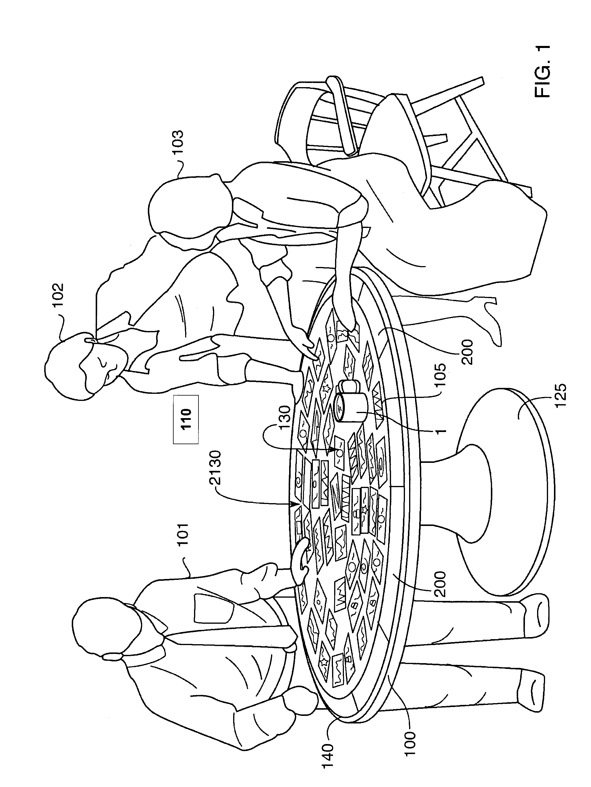
[0035]FIG. 1 shows multiple users 101-103 in the vicinity of a circular graphical user interface 100 operating according to the invention. The users share and interact with a picture presentation in a dynamic and collaborative manner. The system according to the invention displays images 110 on a display surface, i.e., the horizontal tabletop 130 of a circular table 125. The images can be of photographs, videos, computer generated images, icons, documents, or any other displayable source material, hereinafter generally “items.” In the preferred embodiment, the tabletop 130 surface is touch sensitive.

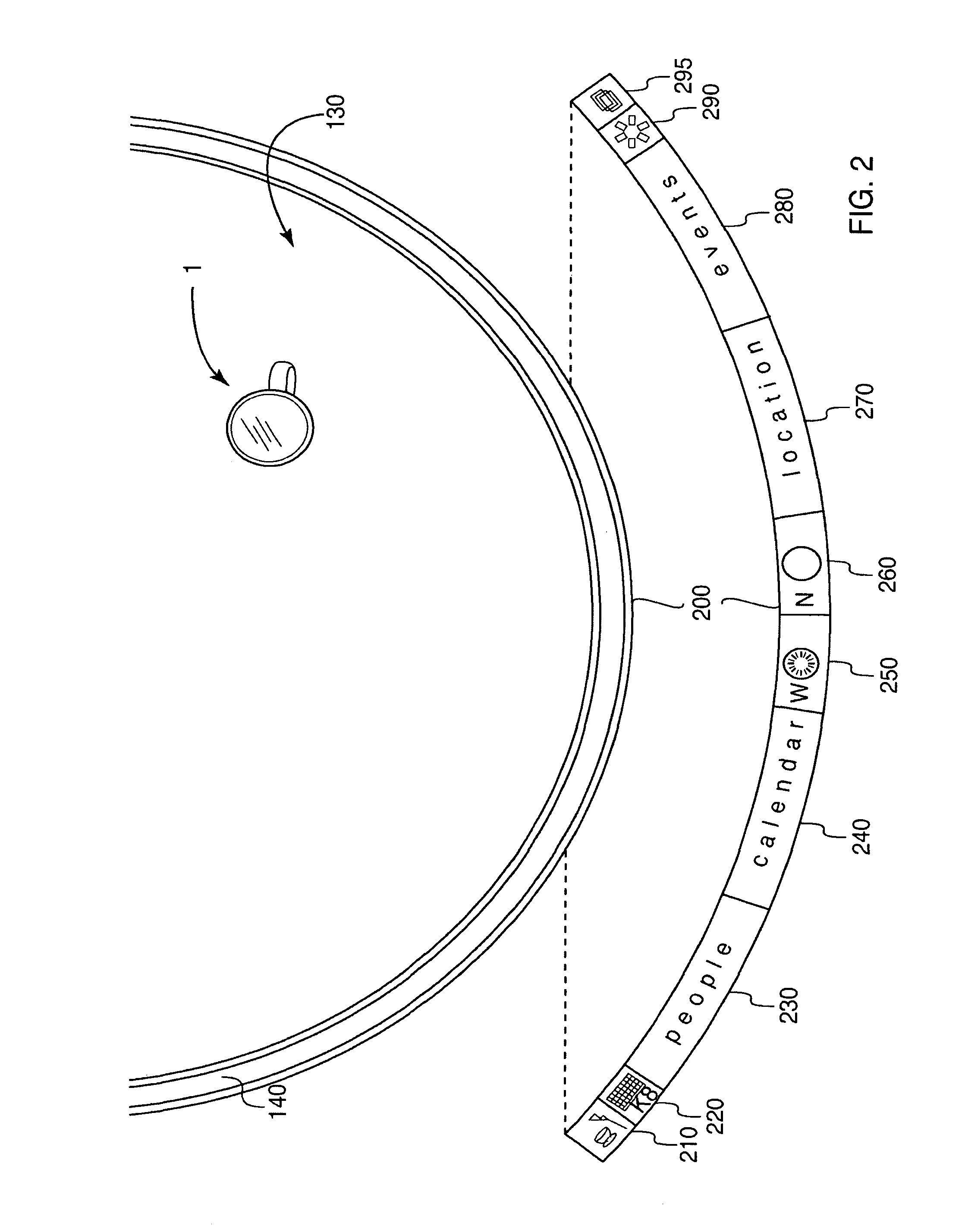
[0036]The interface 100 includes an orientation area 140, and a plurality of control panels (menus) 200. In the preferred embodiment, the orientation area 140 is an annular ring at the periphery of the images. The control panels are composited within the annular ring. There is one control panel or top-level menu for each user. Additional pop-up menus can be added as neede...


PUM


Abstract

A multi-user collaborative graphical user interface has a display area with a horizontal orientation, the display surface is positioned between the multiple users. The display area also has a centroid and a circumference. The display area is partitioned into work areas so that there is one working area for each user of the multiple users. An item is displayed in a particular working area using a global polar coordinate system centered on the centroid.

Description

CROSS-REFERENCE TO RELATED APPLICATION[0001]This is a continuation-in-part of U.S. patent application Ser. No. 10 / 177,004 filed on Jun. 21, 2002 now U.S. Pat. No. 6,894,703, by Vernier et al., which is a continuation-in-part of U.S. patent application Ser. No. 10 / 053,652 “Circular Graphical User Interface” filed by Lesh et al. on Jan. 21, 2002 now U.S. Pat. No. 6,791,530, which is a continuation-in-part of U.S. patent application Ser. No. 09 / 651,002 “Multi-User Interactive Picture Presentation System,” filed by Shen et al. on Aug. 29, 2000 now U.S. Pat. No. 6,545,660.FIELD OF THE INVENTION[0002]The present invention relates generally to graphical user interfaces, and more particularly to multi-user collaborative graphical user interfaces.BACKGROUND OF THE INVENTION[0003]Presentations are an important aspect of many professional and social settings. Executives make presentations to directors, managers conduct meetings with staff, salespersons make presentations to potential customers...

Claims


Application Information

Patent Timeline
IPC IPC(8): G09G5/00G06F17/00G06F3/00G06F3/048G06F3/041G06T1/00
CPCG06F3/048G06F3/1423G06F3/1446G06T1/00
Inventor SHEN, CHIAVERNIER, FREDERIC D.FORLINES, CLIFTON L.
Owner MITSUBISHI ELECTRIC RES LAB INC
Why Eureka
Try Eureka