

Motor drive for a camper jack
a motor drive and jack technology, applied in vehicle maintenance, transportation and packaging, lifting devices, etc., can solve the problem that the prior art screwjack can be slow to operate between a retracted and a retracted position
- Summary
- Abstract
- Description
- Claims
- Application Information
AI Technical Summary
Benefits of technology
Problems solved by technology
Method used
Image

Examples
Embodiment Construction
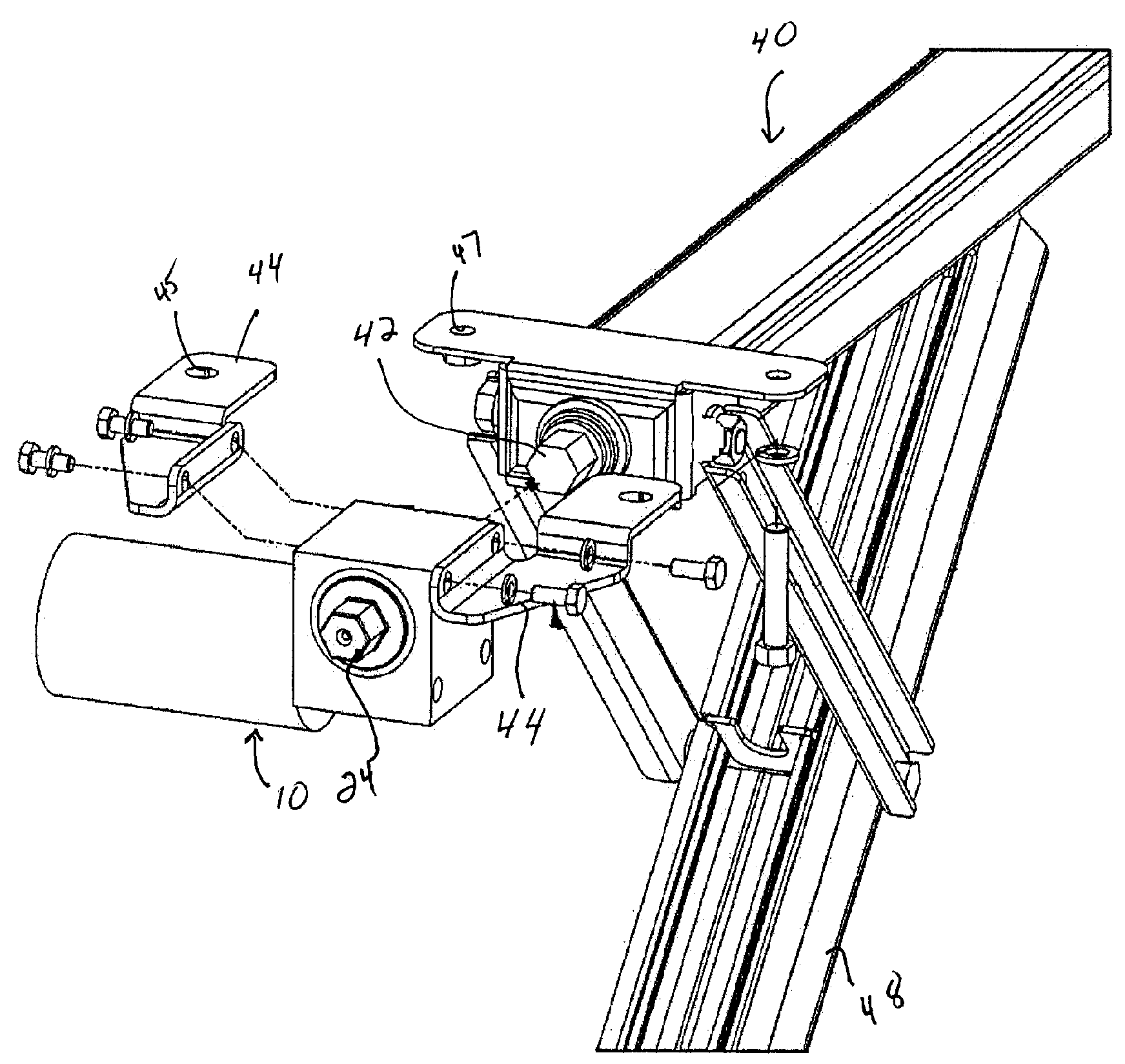
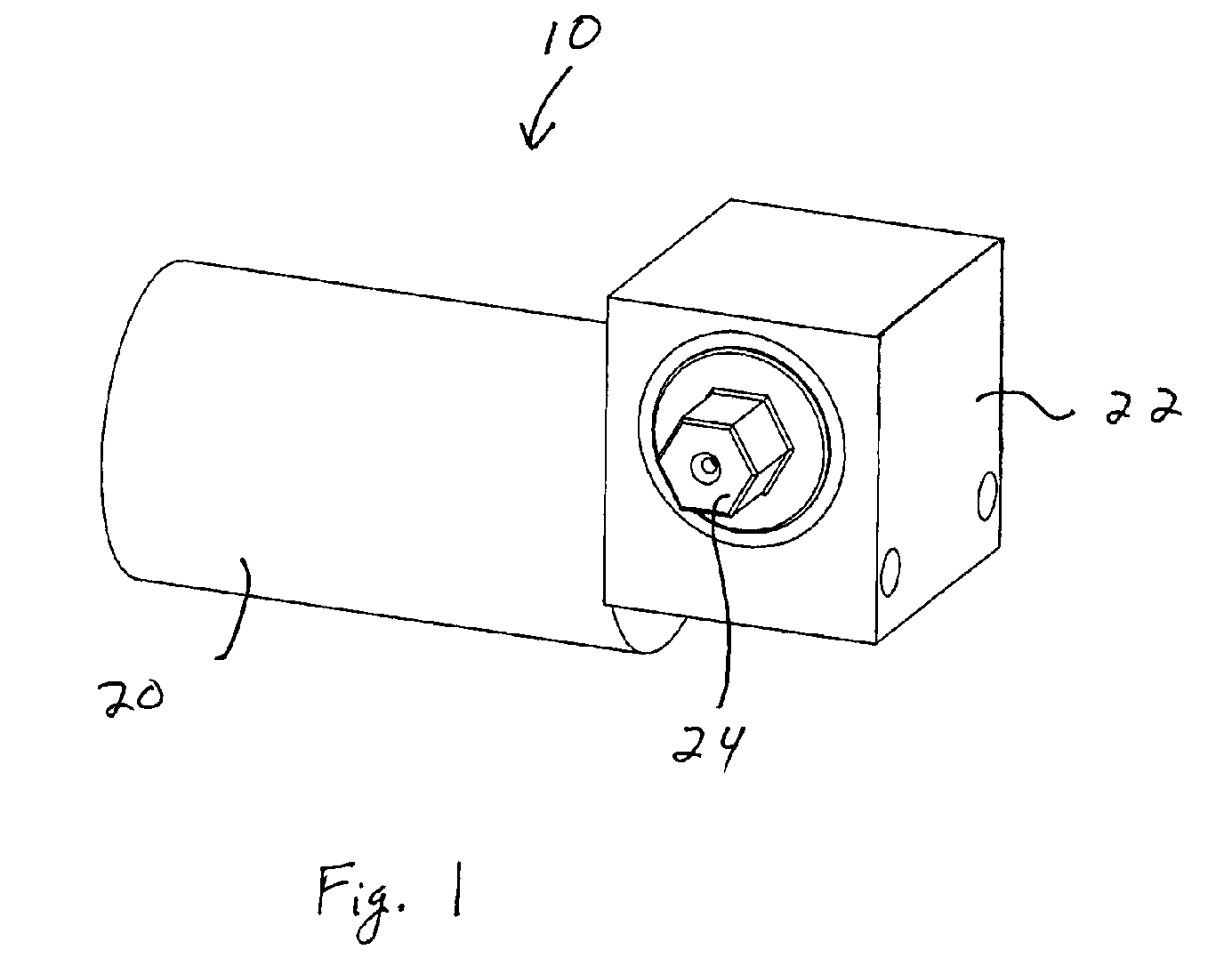
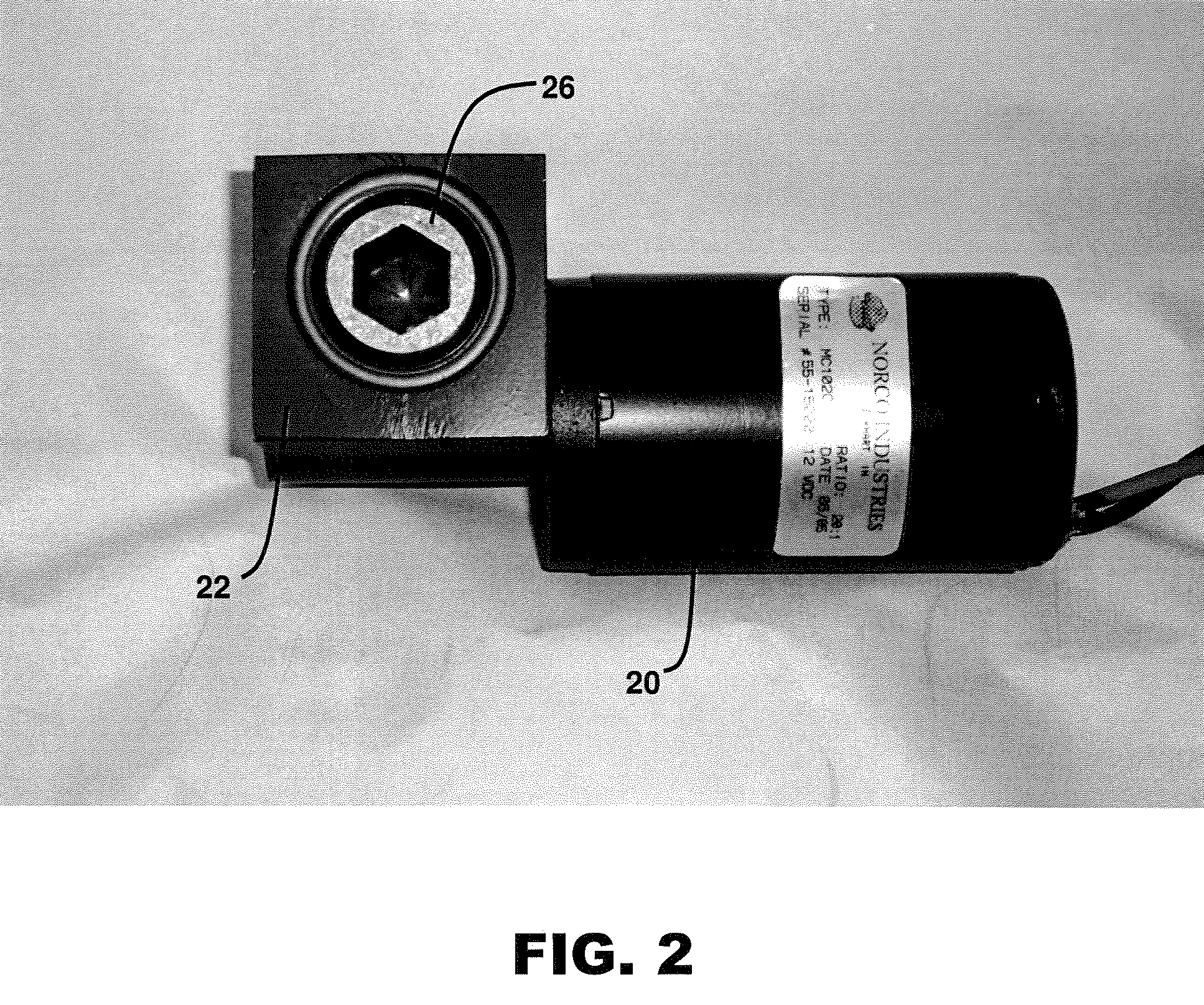
[0017]FIG. 1 illustrates a jack power drive 10 for power operation of a screw jack or camper jack such as the stabilizing jack 40 shown in FIG. 4 or the leveling scissors jack 50 shown in FIG. 6. Drive 10 comprises a motor 20 connected to a gear assembly 22. Preferably, gear assembly 22 is a right angle gear assembly. The motor 20 includes a armature shaft (not shown) that extends into the right angle gear assembly 22. A worm gear 28 (see FIG. 7) fits on the end of the motor armature shaft.
[0018]As shown in FIGS. 7 and 8, the right angle gear assembly 22 includes a housing 25 that is attached to the motor 20. A spur gear shaft (not numbered) is rotatably supported within the housing 25. The spur gear shaft has a centerline 23 that extends at a right angle to a centerline 21 of the motor. A spur gear 27 is mounted on the spur gear shaft and engages the motor worm gear 28. One end of the spur gear shaft terminates in a hex head 24 and the other end of the spur gear shaft terminates in...
PUM
 Abstract
Description
Claims
Application Information