
Processing sensing measurements

a sensing measurement and processing technology, applied in the direction of simultaneous indication of multiple variables, survey, borehole/well accessories, etc., can solve the problem of ignoring remedial or pre-emptive action, and achieve the effect of facilitating selection and easy interpretation of measurements

Active Publication Date: 2010-10-12
SENSORNET
View PDF43 Cites 6 Cited by
  • Summary
  • Abstract
  • Description
  • Claims
  • Application Information

AI Technical Summary

Benefits of technology

"The present invention provides improved apparatus and methods for analyzing measurements from a distributed sensing system for sensing conditions at any range of locations along a one dimensional path. The software receives the measurements, generates a graphical representation of the measurements indicating their location, and a representation of external events at given locations along the path, both scaled and associated to provide a visual correlation between the timing of the measurements and the external events. This enhances the user's ability to interpret the data quickly and draw inferences, leading to cost savings and improved understanding of the conditions being monitored. The software can also be used with different types of sensing systems and can provide a region of interest in the measurements. The graphical representations can be useful for identifying changes in the conditions over time and can help to avoid obscuring information. The invention can be used in various applications, such as monitoring infrastructure, detecting leaks in oil wells, and monitoring environmental conditions."

Problems solved by technology

However this is time consuming and where the measurements can include important changes over short regions, perhaps a few meters, of a long pipe, perhaps many kilometers long, and new readings are obtained every few minutes, then many such changes may be missed and opportunities to take remedial or pre-emptive action may be missed, with costly results.

Method used


Image

  • Processing sensing measurements
  • Processing sensing measurements
  • Processing sensing measurements

Examples


Embodiment Construction

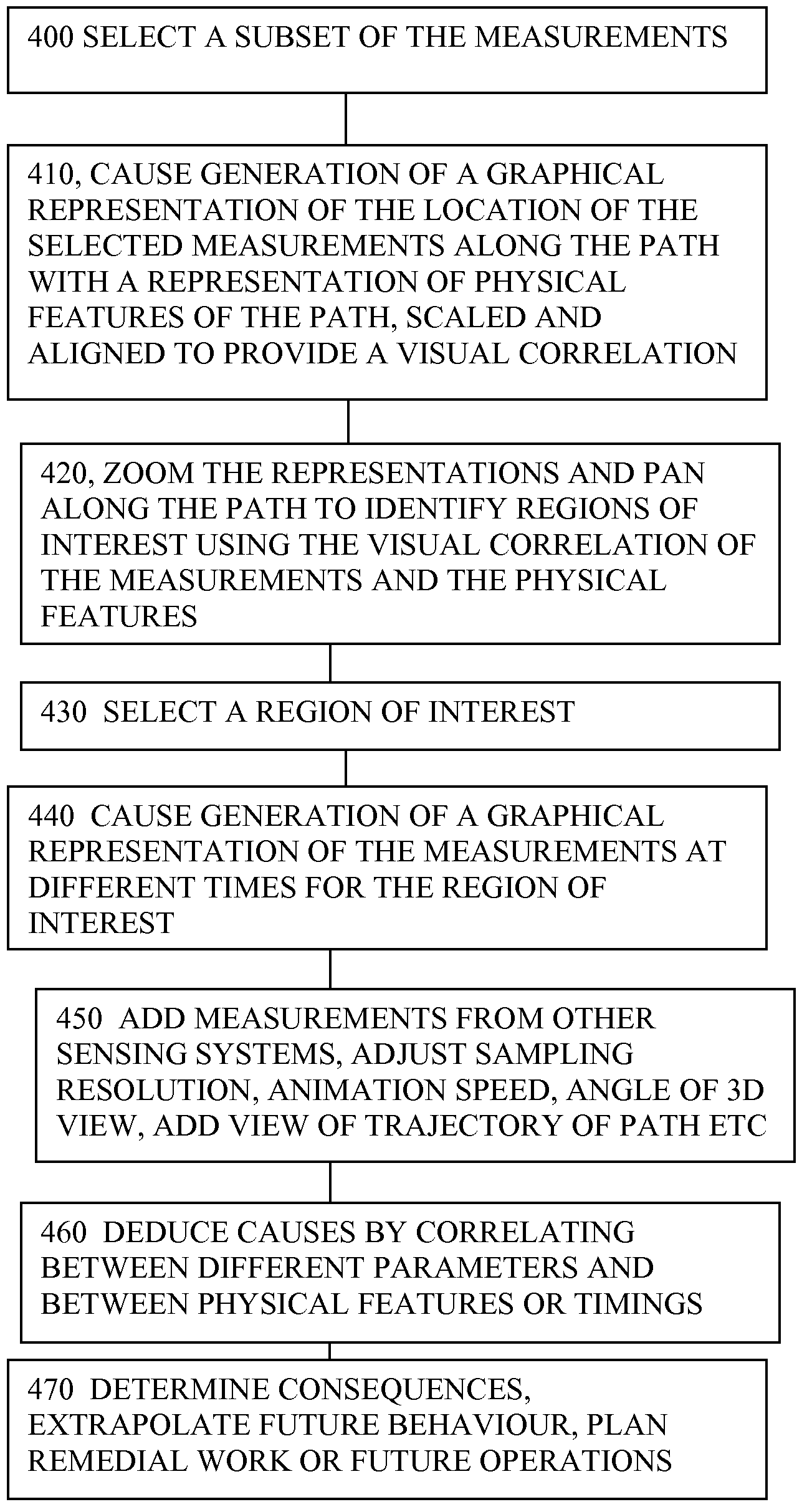
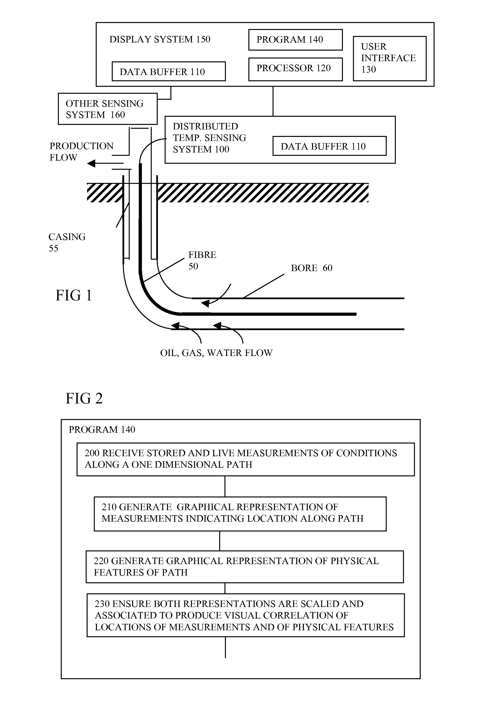
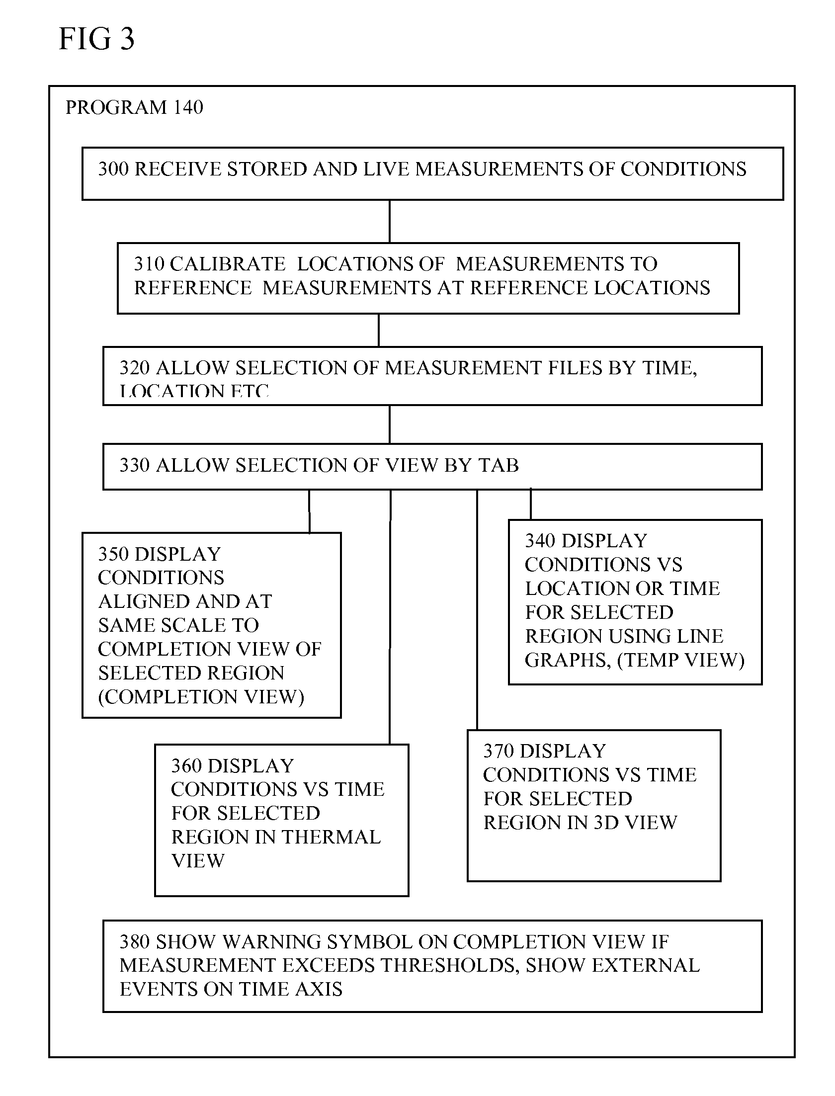
[0040]FIG. 1 System

[0041]The program is a tool for displaying in a user friendly format data obtained from a path in the form of a bore well for example. The data can contain measurements of the conditions in the form of temperature and strain measurements for example, though other measurements are possible. FIG. 1 shows how it can be applied in the context of a display system coupled to a distributed sensing system for a borehole. It shows a sensing fibre 50 installed in a wellbore. The fibre is protected from damage in any suitable manner and is coupled to a distributed sensing system 100 at the wellhead on the surface (or seabed, or sea surface). This optionally has a data buffer 110 for storing the measurements. The bore 60 is typically large enough to take a 10 inch steel casing 55 for a vertical part which can extend anything from hundreds to thousands of meters. The bore typically narrows to a 5 inch bore, 60 and is curved very gradually to extend horizontally for anything up...


PUM


Abstract

Software (140) for processing measurements from a distributed sensing system (100) receives the measurements, and generates a graphical representation of the measurements indicating their location or time sequence, and a representation of locations of physical features along the path (50), or times of external events, the representations being scaled and associated to provide a visual correlation between the locations of the measurements and locations of the physical features, or between times of measurements and times of external events. The enhanced visual correlation can lead to cost savings if more rapid interpretation of large volumes of measurements can give warning of changes such as subsidence of structures, or of ingress of water into oil wells, for example in time for remedial action to be taken.

Description

FIELD OF THE INVENTION[0001]The present invention relates to software for processing of measurements of conditions along a one dimensional path such as a borehole, to computers having such software, to sensing systems for sensing the conditions and processing the measurements, and to methods of analysing such measurements.BACKGROUND[0002]There is a requirement in industry for the measurement of conditions such as strain or temperature at all points over long distances. Typical uses are for monitoring oil and gas wells, long cables and pipelines. The measurements can be displayed or analysed and used to infer the condition of the structures. Distributed temperature sensors (DTS) often use Raman or Brillouin components of scattered light in optical fibres as the means to determine the temperature. Here, light from an optical source is launched into a fibre and the small amount of light that is scattered back towards the source is analysed. By using pulsed light and measuring the retur...

Claims


Application Information

Patent Timeline
Patent Type & Authority Patents(United States)
IPC IPC(8): G06F19/00G06F17/40G01V9/00E21B47/00G01D7/04
CPCE21B47/00G01D7/04G01D7/00
Inventor PARKER, TOM RICHARDLEE, KIN-WEI
Owner SENSORNET
Learn More