Device for the assembly of standard elements intended for the creation of precision mechanical structures

a technology of mechanical structure and standard elements, applied in the direction of sleeves/socket joints, mechanical equipment, manufacturing tools, etc., can solve the problems of high production cost, increased repair cost, and additional cost of stocking grippers

Active Publication Date: 2008-02-19
DELAWARE CAPITAL FORMATION INC
View PDF14 Cites 10 Cited by
  • Summary
  • Abstract
  • Description
  • Claims
  • Application Information

AI Technical Summary

Benefits of technology

[0019]These different standard elements will be designed so as to satisfy the requirements of precision, rigidity and low mass which are necessary for the creation of grippers. Thus, for example, the connecting elements will be created from extruded aluminium-alloy bar. The adjustable standard elements will include precise positioning devices in translation or in rotation. The clamps composed of half collars will be in shape conformity with the end cheek-plates, complying with the precision and rigidity requirements. This will also apply to the assembly of the tenon / mortise type, allowing association of the standard elements and transition elements.

Problems solved by technology

As a consequence, their production cost is high, because the process is one which can be described as artisanal, given the diversity of the mechanical parts to be employed.
In addition, in the event of failure or of damage, the stocking of such grippers constitutes an additional cost, greatly increasing their repair costs.
The drawback of this type of gripper results from the method of assembly of the bar sections, which is performed using assembly bolts and centring pins.
Such an assembly method leads to high production costs for the pin housings and for the threaded orifices, as well as high assembly costs for the mating of the pins with their housings and the number of tightening operations necessary.

Method used


Image

  • Device for the assembly of standard elements intended for the creation of precision mechanical structures
  • Device for the assembly of standard elements intended for the creation of precision mechanical structures
  • Device for the assembly of standard elements intended for the creation of precision mechanical structures

Examples


Embodiment Construction

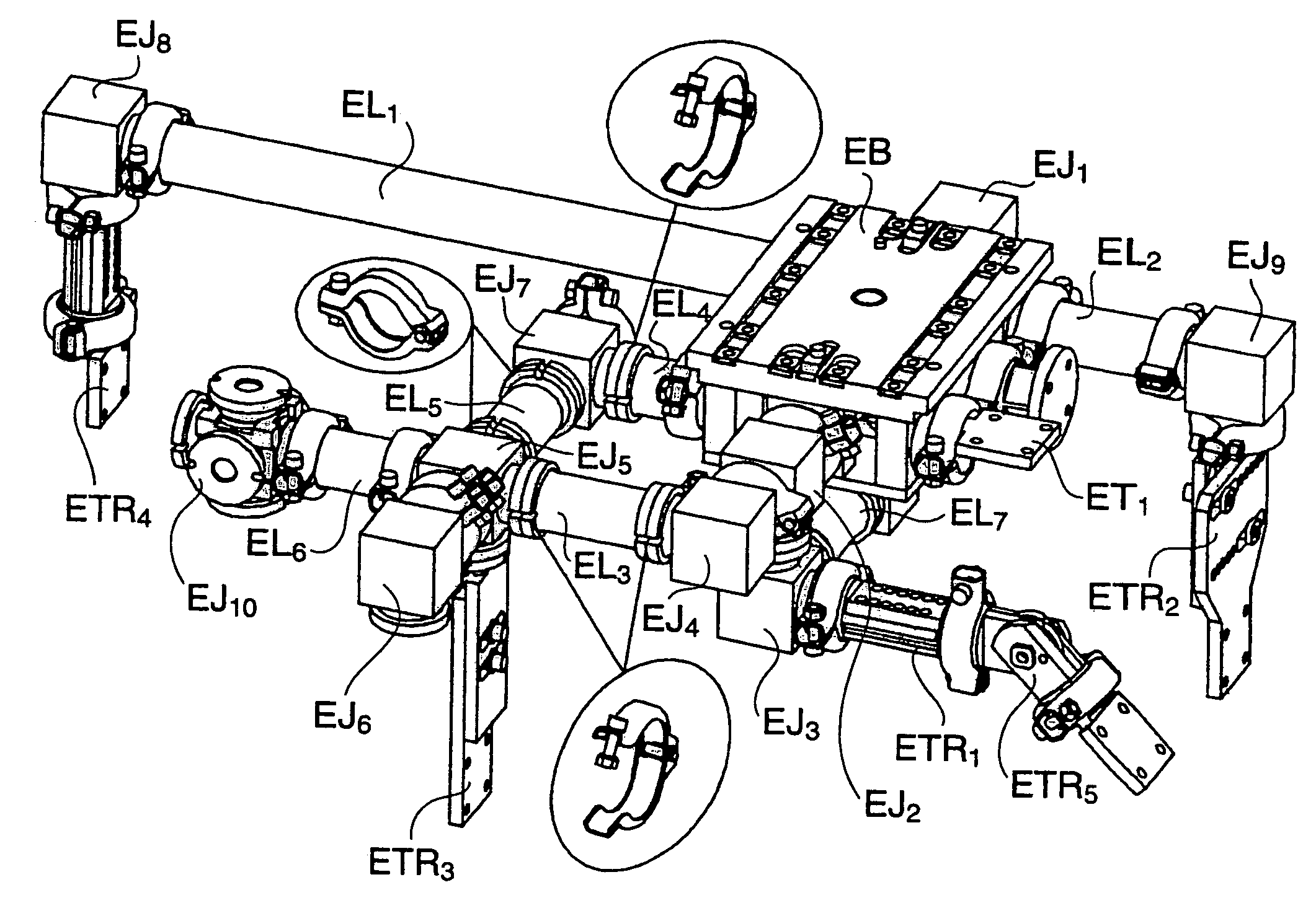
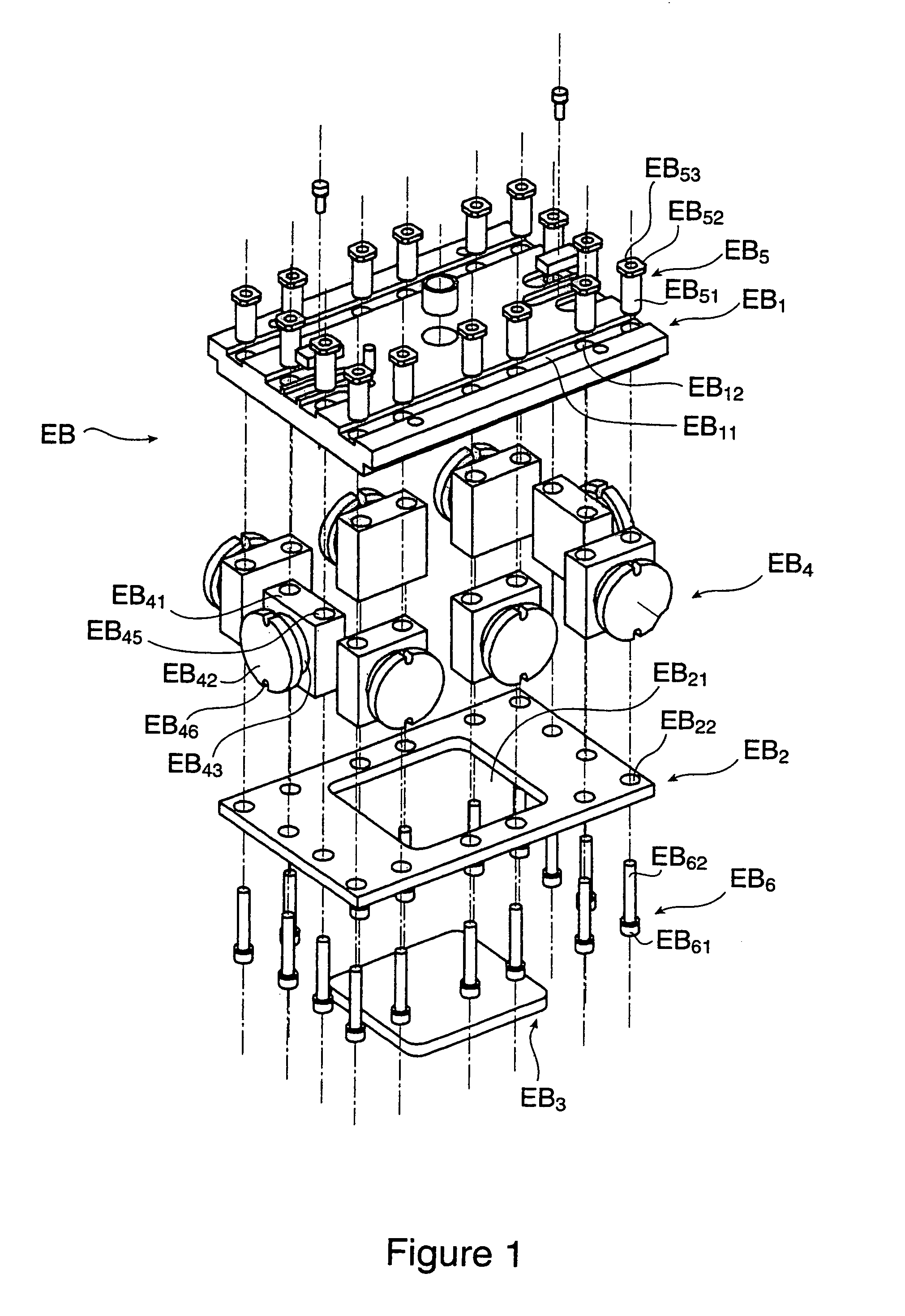
[0029]In the example shown in FIG. 1, the basic element EB essentially includes a top plate EB1, of rectangular shape, a bottom plate EB2 of rectangular shape identical to that of the top plate EB1, an inspection plate EB3 associated with the bottom plate EB2, and a certain number of basic transition elements EB4, of which there are 8 in the present case, positioned between the top plates EB1 and bottom plates EB2.

[0030]Thus, by means of the top plate EB1, the basic element EB is used to fix the assembly of standard elements according to the invention, constituting a gripper, to a fixed support or a mobile support such as the head of a robot.

[0031]The top surface of the aforementioned top plate EB1 will constitute the so-called reference surface of the gripper.

[0032]The top plate EB1, includes grooves EB11, positioned in parallel with the large dimension of said top plate EB1, and cut into the top face of said top plate EB1. Said grooves EB11, also include circular orifices EB12 pas...


PUM

PropertyMeasurementUnit
angleaaaaaaaaaa
angleaaaaaaaaaa
angleaaaaaaaaaa

Abstract

A device for the assembly of at least two standard elements of a precision mechanical structure by a linking element, where the first standard element includes a reference surface, while the second standard element includes a bearing surface which has to be positioned with precision in an orthonormal coordinate system associated with the aforementioned reference surface, given that the connection between the linking element and at least one of the standard elements includes two contact faces provided on the linking element and the standard element. A clamp composed of two half collars, and presenting shapes which interlock with the corresponding shapes of the linking element and of the standard element in such a way that the clamping of the two half collars causes the application and the centering of the two aforementioned contact faces against each other.

Description

BACKGROUND OF THE INVENTION[0001]1. Field of the Invention[0002]This present invention concerns a device for the assembly of standard elements intended for the creation of precision mechanical structures.[0003]2. Description of Related Art[0004]It applies in particular, but not exclusively, to the creation of tools for the gripping of mechanical parts intended in particular for the automobile industry. It is usable in particular on assembly lines for parts of the bodywork of automobiles which require gripping tools or grippers, which are firmly attached to fixed supports or mobile supports such as the heads of robots. It is used to position, with precision and in a repeatable manner, the aforementioned mechanical parts during their assembly on automobile assembly lines. It also allows said grippers to conform to the nature of the mechanical parts to be processed and to the type of operation to be performed on said mechanical parts.[0005]We know in fact that such grippers are designe...

Claims


Application Information

Patent Timeline
Patent Type & Authority Patents(United States)
IPC IPC(8): B23P19/00E04B1/58F16L21/06F16L23/10
CPCF16L23/10B25J15/0061F16L21/065E04B1/585E04B2001/5868Y10T29/53435
Inventor CARASSO, PHILIPPELENEVEU, BRUNONORJOUX, LAURENTROCTON, PHILIPPE
Owner DELAWARE CAPITAL FORMATION INC
Why Eureka
Try Eureka