Electric milling machine

a technology of electric milling machine and floor milling machine, which is applied in the direction of manufacturing tools, roads, roads, etc., can solve the problems of large machines that cannot fit in many buildings, are difficult, if not impossible to use indoors, and are powerful enough to treat or remove them. to achieve the effect of facilitating the ability to mill surfaces

Inactive Publication Date: 2008-02-19
PREP ENG
View PDF14 Cites 14 Cited by
  • Summary
  • Abstract
  • Description
  • Claims
  • Application Information

AI Technical Summary

Benefits of technology

[0006]The present invention provides a milling machine having a housing including a frame, a front wheel assembly supporting the housing, at least a first rear wheel assembly and a second rear wheel assembly supporting the housing, a milling drum mounted within the housing and extending below the housing, and an electric motor for providing rotational power to at least one hydraulic system for operating milling machine functions. At least the first rear wheel assembly is ideally switchable between a first position to provide stability and a second position to allow the milling machine to mill flooring surfaces near walls or other obstructions and in corners and other tight spaces. The milling drum is also ideally located in a rear corner of the milling machine adjacent the switchable first rear wheel assembly to further facilitate the ability to mill surfaces in corners and other tight spaces in buildings. The milling machine preferably further includes a dust collection system mounted substantially within the housing to provide dust-free operation. The electric motor is also ideally mounted within the housing to provide a compact, dust-free and emissions-free milling machine for indoor use.
[0009]The present invention has many advantages over the prior art. First, the use of an electric motor not only reduces but eliminates the emissions associated with prior art internal combustion engines. The combination of the electric motor as the prime mover together with the hydraulic system provides an unsurpassed power to size ratio for the overall unit. The use of an on-board electric motor and dust collection system, moreover, allows for an emissions-free milling operation using a single, compact machine. Furthermore, the switchable first rear wheel assembly and the location of the milling drum in the rear corner adjacent the first rear wheel assembly of the present invention provides unexcelled stability while allowing the machine to easily maneuver into corners and other tight spaces, thereby allowing more of the flooring to be removed using the machine and reducing the amount of flooring that will need to be removed by other, more time-consuming means such as the use of a jackhammer. The use of an all-wheel drive system provides further advantages in that the milling machine of the present invention has positive traction, holds cutting positions better, and more easily climbs onto trailers for transport from one location to another.

Problems solved by technology

Because ground and floor surfaces are among the hardest construction materials, the milling machines powerful enough to treat or remove them must normally be very large and heavy.
Such machines work well for outdoor surfaces and surfaces in open areas, but are difficult, if not impossible, to use indoors.
Very large machines will not fit inside many buildings, and the ventilation systems in many buildings are not equipped to deal with the exhaust produced by internal combustion engines.
In the event that the machine will fit into the building, it can still be difficult to remove much of the floor surface because the machines cannot accomplish a milling function near walls or into corners and other tight spaces.
Although some milling machines have been adapted or designed for use indoors, like those described above, those prior art milling machines still have significant limitations.
Most significantly, the prior art milling machines do not provide a single, compact machine that effectively reduces both pollution and dust emissions.
Additionally, it is still difficult if not impossible, using prior art milling machines, to reach corners and other tight spaces in the building.

Method used


Image

  • Electric milling machine
  • Electric milling machine
  • Electric milling machine

Examples


Embodiment Construction

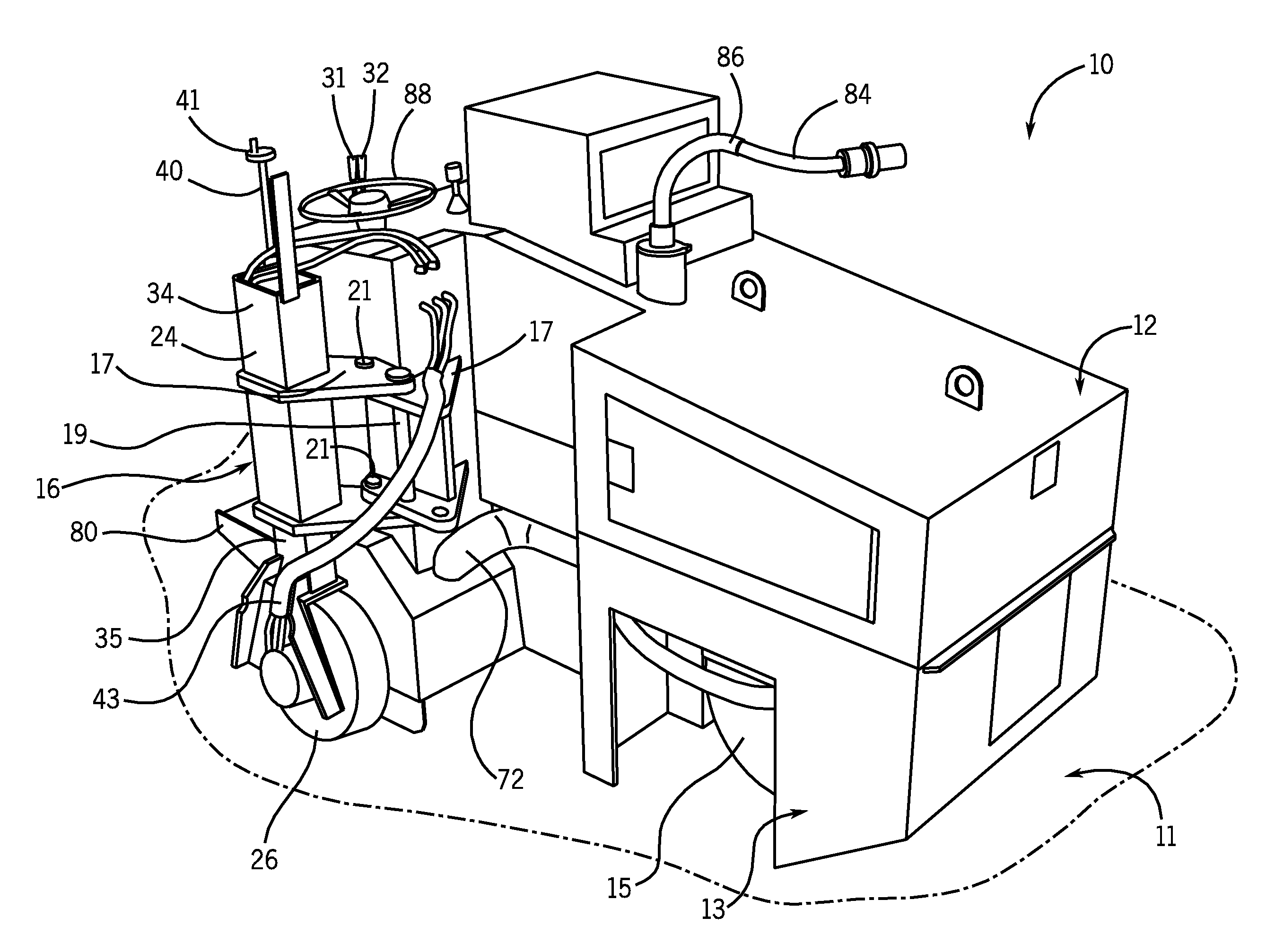
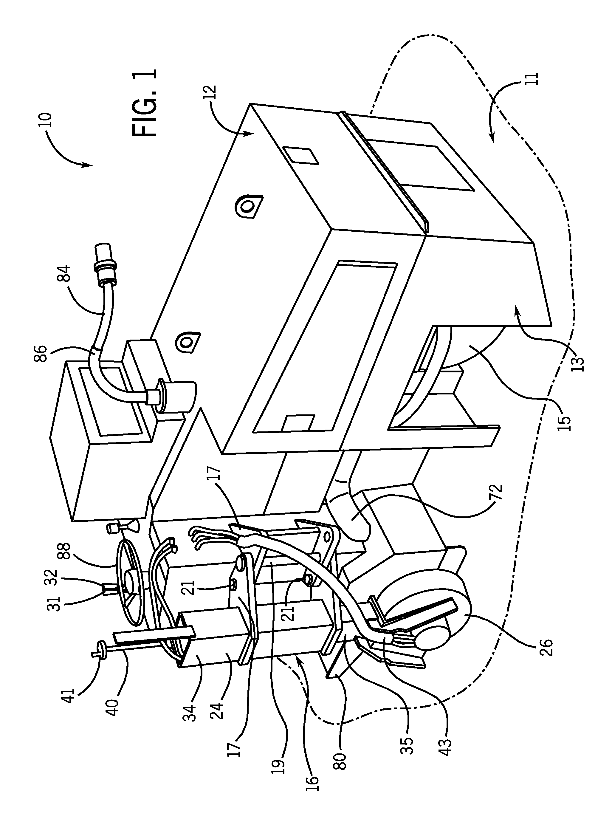
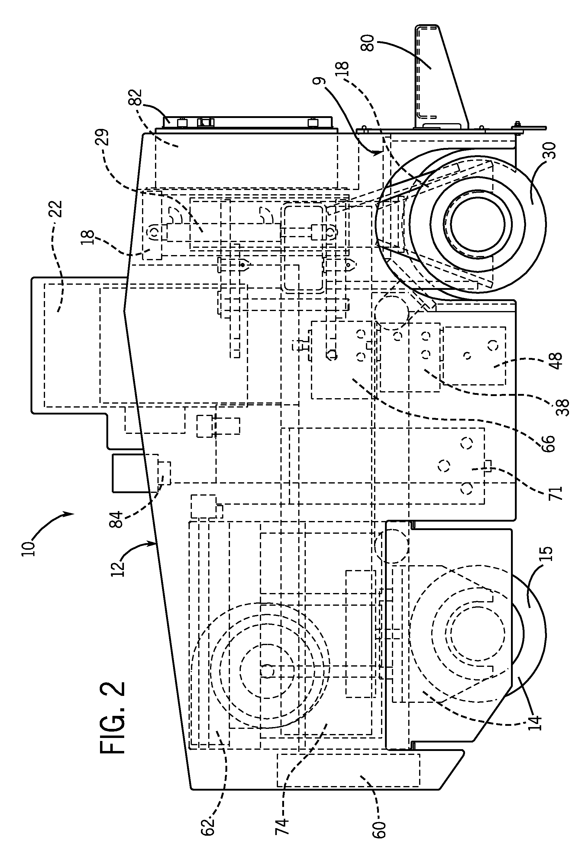
[0019]Referring now to the drawings, a milling machine 10 constructed according to one embodiment of the present invention includes a housing 12 including a frame 9. The housing 12 is supported by a front wheel assembly 14, a first rear wheel assembly 16, and a second rear wheel assembly 18. The housing 12 contains a milling drum 20 mounted within the housing 12 and extending below the housing 12 for engagement with the flooring surface 11, and an electric motor 22 that powers hydraulic systems for driving the milling drum 20, the first and second rear wheel assemblies 16, 18, and auxiliary systems such as a dust collection system. The housing 12 is ideally a compact housing that allows the milling machine to easily fit inside buildings. In the preferred embodiment, the housing 12 is under 7 feet tall, under 10 feet long, and under 6 feet wide; however, other sizes that allow the milling machine to easily be used indoors are also contemplated by the present invention.

[0020]The first...


PUM

PropertyMeasurementUnit
widthaaaaaaaaaa
widthaaaaaaaaaa
widthaaaaaaaaaa

Abstract

A milling machine comprising a housing including a frame, a front wheel assembly supporting the housing, at least a first rear wheel assembly and a second rear wheel assembly supporting the housing, a milling drum mounted within the housing and extending below the housing, and an electric motor for providing power to at least one hydraulic system for operating milling machine functions. The first rear wheel assembly is ideally switchable between a first position and a second position to allow the milling machine to reach corners and other tight spaces in a building. The milling machine preferably further includes a dust collection system mounted within the housing to provide dust-free operation. The electric motor is also ideally mounted within the housing to provide a compact, dust-free and emissions-free milling machine for indoor use.

Description

BACKGROUND OF THE INVENTION[0001]The present invention relates generally to the field of milling machines, and more particularly to an electric floor milling machine for indoor use.[0002]Milling machines are commonly used to treat ground and floor surfaces, such as concrete, and to remove floor coverings, such as ceramic tiles and epoxy coatings. Because ground and floor surfaces are among the hardest construction materials, the milling machines powerful enough to treat or remove them must normally be very large and heavy. The power sources for such large and heavy machines are typically internal combustion engines, such as gasoline or diesel engines. Such machines work well for outdoor surfaces and surfaces in open areas, but are difficult, if not impossible, to use indoors. Very large machines will not fit inside many buildings, and the ventilation systems in many buildings are not equipped to deal with the exhaust produced by internal combustion engines. In the event that the mac...

Claims


Application Information

Patent Timeline
Patent Type & Authority Patents(United States)
IPC IPC(8): E01C23/088
CPCB24B7/188B24B55/06B28D1/18
Inventor TROUDT, DONALD DEASTON, JOHNPLATEK, ROBERT A.VESELY, MARK E.PAULICK, MICHAEL A.
Owner PREP ENG
Why Eureka
Try Eureka