
Fire detection system

a detection system and fire detection technology, applied in fire alarms, fire alarm radiation actuation, instruments, etc., can solve the problems of halon producing toxic products, affecting the cleaning process, and affecting the quality of the fire alarm,

Active Publication Date: 2008-02-19
ROSEMOUNT AEROSPACE
View PDF23 Cites 41 Cited by
  • Summary
  • Abstract
  • Description
  • Claims
  • Application Information

AI Technical Summary

Problems solved by technology

However, the Halon material of the current systems contains an ozone depleting material which may leak from the storage compartment and into the environment upon being activated to suppress a fire.
Also, Halon produces toxic products when activated by flame.
In addition, any time the fire suppressant material is dispensed to flood and blanket a storage area as a result of a fire indication from a fire detection system, it leaves a residue which covers the storage area or compartment and all of its contents.
As a result of this situation, a very costly and time consuming clean-up is promptly performed with each dispensing of suppressant material.
This unscheduled servicing of the aircraft is very costly to the airlines and inconveniences the passengers thereof.
The problem is that some activations of the fire suppressant system result from false alarms of the fire detection system, i.e. caused by a perceived fire condition that is something other than an actual fire.

Method used


Image

  • Fire detection system
  • Fire detection system
  • Fire detection system

Examples


Embodiment Construction

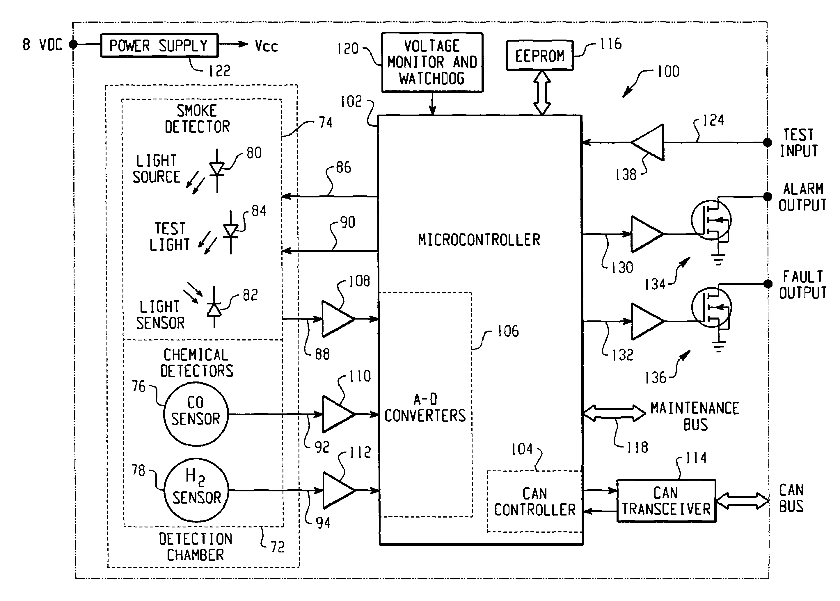
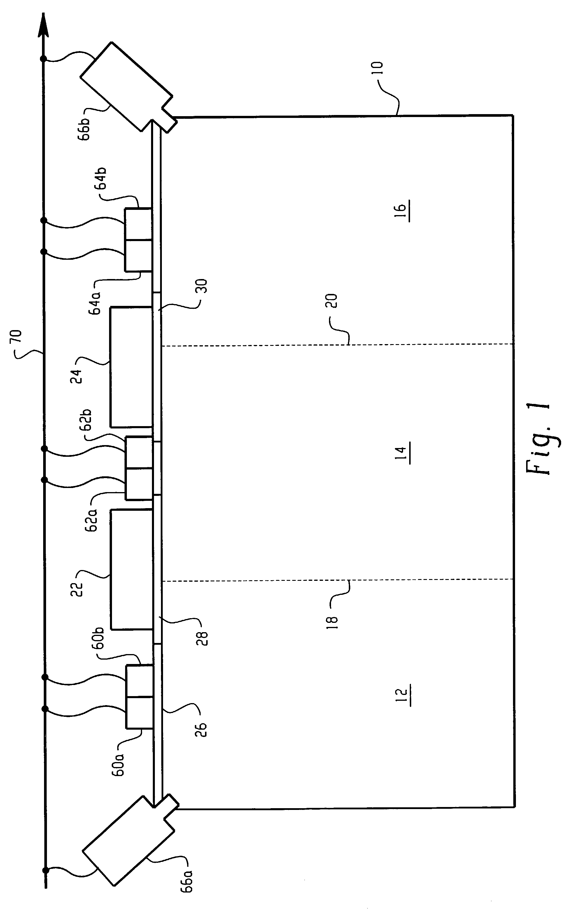
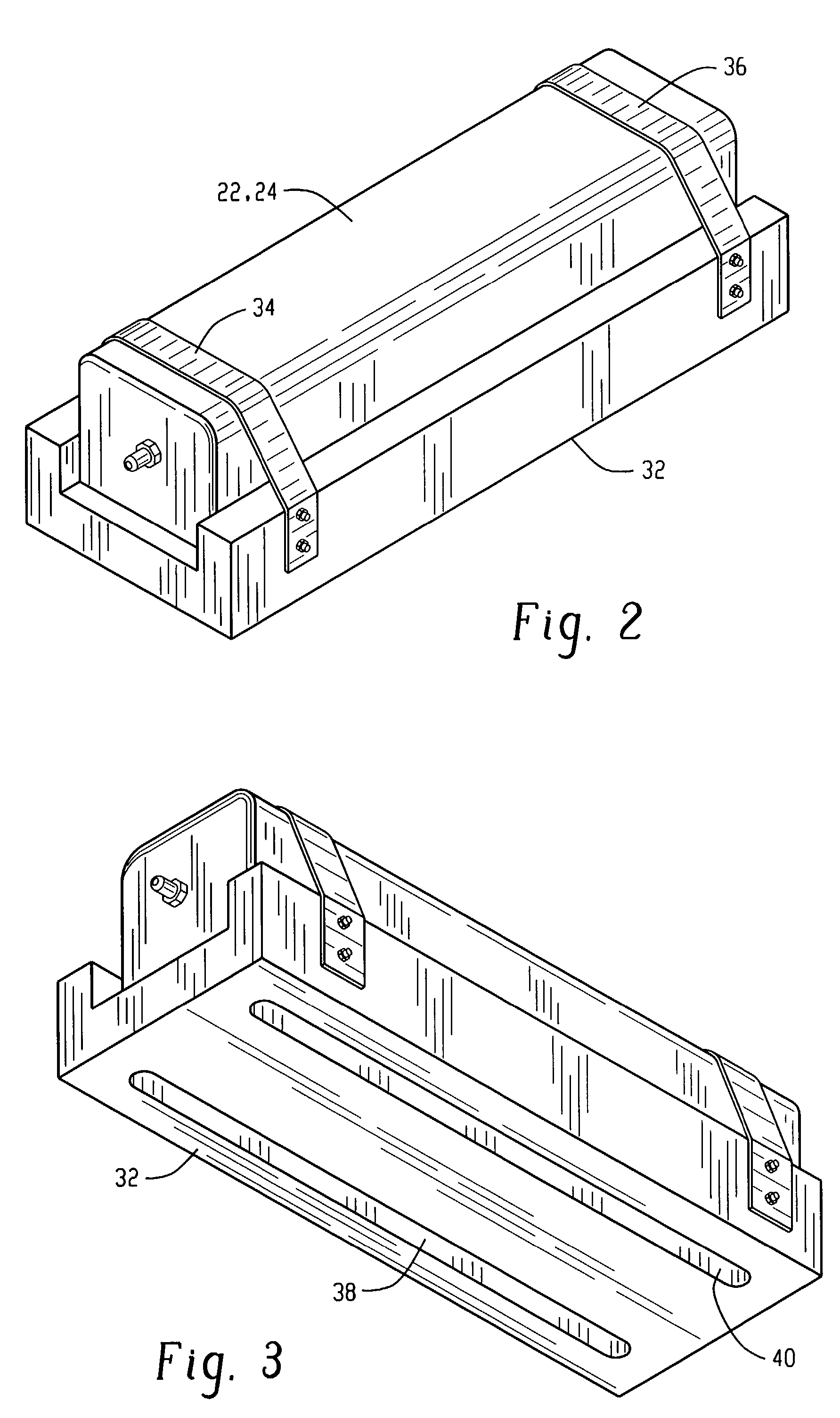
[0018]A sketch of a fire detection and suppression system for use at a storage area or compartment suitable for embodying the principles of the present invention is shown in cross-sectional view in FIG. 1. Referring to FIG. 1, a storage compartment 10 which may be a cargo hold, bay or compartment of an aircraft, for example, is divided into a plurality of detection zones or cavities 12, 14 and 16 as delineated by dashed lines 18 and 20. It is understood that an aircraft may have more than one cargo compartment and the embodiment depicted in FIG. 1 is merely exemplary of each such compartment. It is intended that each of the cargo compartments 10 include one or more gas generators for generating a fire suppressant material. In the present embodiment, a plurality of hermetically sealed, gas generators depicted by blocks 22 and 24, which may be solid propellant in ultra-low pressure gas generators, for example, are disposed at a ceiling portion 26 of the cargo compartment 10 above vent...


PUM


Abstract

A fire detection system for an enclosed area comprises: at least one infrared (IR) imager for generating infrared images of at least a portion of the enclosed area, for determining from the images that a fire is perceived present in the enclosed area, and for generating a first signal indicative of the perceived presence of fire; at least one fire detector for monitoring at least a portion of the enclosed area, the fire detector comprising at least one fire byproduct chemical sensor for generating at least one second signal representative of the presence of at least one fire byproduct chemical in the enclosed area; and a controller governed by the first and second signals to confirm that a fire is present in the enclosed area. In one embodiment, the enclosed area is divided into a plurality of detection zones with at least one fire detector disposed at each detection zone. In this embodiment, the controller includes a first controller governed by the second signals for generating a third signal indicative of the presence of fire in the corresponding detection zone; and a second controller governed by the first and third signals to confirm that a fire is present in at least one detection zone of the enclosed area.

Description

[0001]This application claims the benefit of the provisional patent application No. 60 / 323,824 filed Sep. 21, 2001.BACKGROUND OF THE INVENTION[0002]The present invention is directed to fire detection systems, in general, and more specifically to a system capable of detecting a fire in a storage area accurately and reliably, with a controller which is governed by at least one IR imager and at least one fire detector disposed at the storage area to confirm the presence of a fire in the storage area.[0003]It is of paramount importance to detect a fire in an unattended, storage area or enclosed storage compartment at an early stage of progression so that it may be suppressed before spreading to other compartments or areas adjacent or in close proximity to the affected storage area or compartment. This detection and suppression of fires becomes even more critical when the storage compartment is located in a vehicle that is operated in an environment isolated from conventional fire fighti...

Claims


Application Information

Patent Timeline
IPC IPC(8): H04N7/18A62C35/08A62C37/40A62C99/00G08B17/12G08B29/18G08B29/20
CPCA62C35/08A62C37/40A62C99/0045G08B17/125G08B25/002G08B29/183G08B29/188G08B29/20
Inventor MILLER, MARK S.WIEGELE, THOMAS G.
Owner ROSEMOUNT AEROSPACE
Learn More