Fire suppression system

a fire suppression and system technology, applied in fire rescue, spray nozzles, spraying apparatus, etc., can solve the problems of short protection time, insufficient oxygen deprivation and suffocation, and too strong fires, so as to prevent or lessen the possibility of sudden eruption

Active Publication Date: 2016-09-15
ENK SR WILLIAM ARMAND
View PDF1 Cites 29 Cited by
  • Summary
  • Abstract
  • Description
  • Claims
  • Application Information

AI Technical Summary

Benefits of technology

[0022]Another advantage of the present invention is the rigid foam system will control a fire for a limited time even if depressurization occurs in the enclosure containing the freight. Because there is an exposure to a growing fire during the time to depressurize the aircraft and for the aircraft to reach a cabin altitude where there is insufficient oxygen to support a fire, the present invention provides effective fire protection during the period of time from the beginning of a fire until reaching a cabin altitude where there is no longer sufficient oxygen for a fire to continue. Further, after a fire event has occurred, the present invention provides effective fire protection during a de-pressurized aircraft's descent when the air density in the affected cargo compartment(s) increases again to the point where a fire may re-ignite and cause further damage were it not for the presence of the present invention Further, once deployed, the present invention provides protection to 1st and second responders because it contains the fire, smoke, and fumes and may prevent or lessen the possibility of an sudden eruption of a dangerous fire or explosion.
[0023]Other aspects and advantages of the present invention will be apparent from the following detailed description of the preferred embodiments and the accompanying drawing figures.BRIEF DESCRIPTION OF THE SEVERAL VIEWS OF THE DRAWING
[0024]In the accompanying drawings, which form a part of the specification and are to be read in conjunction therewith in which like reference numerals are used to indicate like or similar parts in the various views:
[0025]FIG. 1 is a schematic view of one embodiment of the fire suppression system of the present invention;
[0026]FIG. 1A is a front view of a valve of the embodiment of the fire suppression system of FIG. 1.
[0027]FIG. 2 is a perspective view of one embodiment of the fire suppression system of the present invention;

Problems solved by technology

Some agents proposed in earlier methods have properties which are toxic, corrosive, subject to freezing, have short-lived durations of protection (usually due to the inability of the ULD to sufficiently overcome leakage) or have a combination of these characteristics, all detracting from a reliable and simple method of controlling fires likely to occur today in a ULD.
There are cases, however, where a fire is too strong and oxygen deprivation and suffocation simply is not enough.
In addition, once depressurization of the aircraft occurs the necessary amount of foam or gas mixture may leak out, or be forced out, of the aircraft and therefore not sufficiently extinguish the fire; and / or when the aircraft descends the air density inside will again be sufficient to support a fire.
None of the earlier crew interface means provide protection of the interface device that detects the fire and communicates with the crew from explosions and projectiles capable of damaging the interface device; thus, preventing the interface means from performing its intended functions.
Moreover, weight, volume, and the cost to maintain products in airworthy condition are all critical in air freight operations.
However, these proposed systems are not optimal because they add unnecessary weight to the overall load of the air freight plane because the additional fire protection may not be needed for all freight depending on type.
Further, there are also no standards or practices to determine, before each use, the airworthiness of a ULD with such added fire suppression means.
Built-in systems also pose cost and reliability concerns.
The costs to develop, certify, and maintain built-in systems are often substantial.
ULDs are typically subject to very rough treatment and storage conditions.
Thus, the source of a fire is most likely to be the freight inside of the ULD, and often the risk may be limited to only a few ULDs on each carrier that contain materials, such as lithium batteries, that pose substantial and unique fire threats.
Similar, pallets or boxes in trailers of one of the millions of over-the-road tractors may include materials that pose a fire risk.
Once the lithium (or other long range) batteries are exposed or broken, there is the chance of spontaneous ignition and the fires of these metals are very difficult to extinguish.
Otherwise, a fire is much more difficult to bring under control and it causes much more damage once the fire is in the heat and flame phase.
Since depressurizing the cargo compartment(s) of a freighter aircraft is one traditional means to suppress a fire, the traditional fire suppression system (Halon) cannot be activated until after these compartments are depressurized.
Otherwise, if the traditional fire suppression system is first deployed the extinguishing agent will be forced out of the airplane and what agent remains, if any, will be too diluted to be effective.
Thus, there is an exposure to a growing fire during the time to depressurize the aircraft and for the aircraft to reach a cabin altitude where there is insufficient oxygen to support a fire.
The aforementioned problems and needs similarly apply to many other situations where fire protection is a concern.
For example, wind turbines have battery storage and mechanical compartments at risk of starting a fire within the wind turbine.
Storage units and facilities, particularly battery storage units, are also susceptible to fires.

Method used


Image

  • Fire suppression system
  • Fire suppression system
  • Fire suppression system

Examples


Embodiment Construction

[0037]The following description of the invention illustrates specific embodiments in which the invention can be practiced. The embodiments are intended to describe aspects of the invention in sufficient detail to enable those skilled in the art to practice the invention. Other embodiments can be utilized and changes can be made without departing from the scope of the present invention.

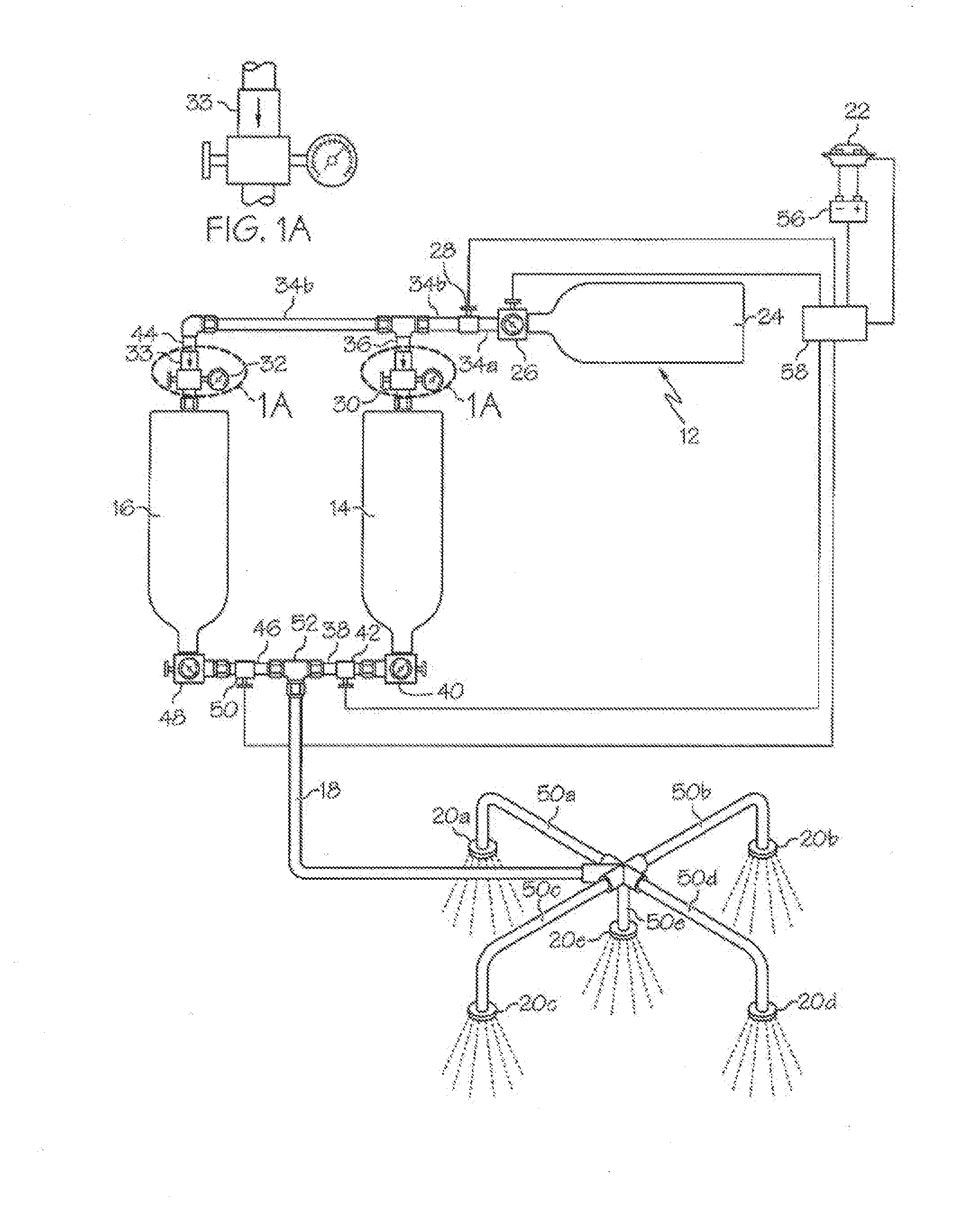
[0038]The present invention is directed to a fire suppression system 10 used to disperse a two part fire retarding foam chemical agent. Fire suppression system 10 of the present invention comprises a pressure source 12, a first component tank 14, a second component tank 16, a mixing tube 18, at least one nozzle 20, and a heat / smoke sensor 22. FIG. 1 illustrates an embodiment of the present invention wherein pressure source 12 comprises a compressed gas tank 24. Compressed gas tank 24 includes a volume of gas under pressure so as to be a propellant for the components of tanks 14 and 16. Compressed gas t...


PUM


Abstract

A fire suppression system for a fire zone including a first tank containing a first liquid component of a two-part foam and a second tank containing a second liquid component of the foam. The system includes at least one liquid component release device configured to be selectively capable of releasing the first and second components from their respective containers upon receipt of a signal from a fire detector upon detection of a fire. The two-part foam components are propelled through the system by a pressurized propellant that, upon release of the release device, causes the exit of the foam components from their respective tanks, through a mixing conduit to at least one nozzle. The nozzle is configured to spray the liquid component foam mixture into the fire zone wherein the foam cures into a substantially semi-rigid, closed cell foam that is substantially impermeable and may have charring and / or intumescence properties.

Description

CROSS-REFERENCE TO RELATED APPLICATIONS[0001]This application is a continuation-in-part of and claims priority to U.S. patent application Ser. No. 14 / 641,055, filed on Mar. 6, 2015 to William A. Enk, Sr. entitled “Fire Suppression System,” currently pending, which is a Continuation of and claims priority to U.S. patent application Ser. No. 13 / 336,298, filed on Dec. 23, 2011 to William A. Enk, Sr. entitled “Fire Suppression System,” now issued as U.S. Pat. No. 8,973,670, which claims priority to U.S. Provisional Patent Application No. 61 / 428,614 having a filing date of Dec. 30, 2010, and U.S. Provisional Patent Application No. 61 / 433,313 having a filing date of Jan. 17, 2011. The entire disclosures, including the specifications and drawings, of all above-referenced applications are incorporated herein by reference.BACKGROUND OF THE INVENTION[0002]A notice of proposed rulemaking has been issued by U.S. DOT that may require one or more of several additional measures to protect aircraft...

Claims


Application Information

Patent Timeline
Patent Type & Authority Applications(United States)
IPC IPC(8): A62C5/02A62C3/00B05B1/18A62C35/13A62C35/02B05B12/08A62C3/08A62C37/40
CPCA62C5/024A62C3/08A62C3/002B05B1/185A62C35/13A62C35/023B05B12/087A62C37/40A62C5/02A62C99/0036
Inventor ENK, SR., WILLIAM ARMAND
Owner ENK SR WILLIAM ARMAND
Why Eureka
Try Eureka