Reciprocatory dry shaver

a shaver and recoil technology, applied in the direction of metal working devices, etc., can solve the problems of inability to drive the oscillator in conformity the inner cutter's vertical movement is in contradiction with the arc of the outer cutter, etc., and achieves the effect of efficient shaving

Active Publication Date: 2008-02-26
MATSUSHITA ELECTRIC WORKS LTD
View PDF22 Cites 25 Cited by
  • Summary
  • Abstract
  • Description
  • Claims
  • Application Information

AI Technical Summary

Benefits of technology

[0003]In view of the above problem, the present invention has been accomplished to provide an improved reciprocatory dry shaver which is capable of driving an inner cutter smoothly along an arcuately curved outer cutter for efficient shaving. The dry shaver in accordance with the present invention includes a shaving head carrying an elongated outer cutter which is arcuately curved along its length, and an inner cutter driven to reciprocate along the length of the outer cutter in hair shearing engagement with the outer cutter. An actuator is mounted in the shaving head for driving the inner cutter. The actuator is configured to include an oscillator which reciprocates in the lengthwise direction of the outer cutter and carries a joint for driving connection to the inner cutter. Also included in the actuator is a resilient coupling link which supports the oscillator to the shaving head in order to allow the oscillator to reciprocate relative to the shaving head. The feature of the present invention resides in that the resilient coupling link has its upper end coupled to the oscillator and [the other] its lower end anchored to the shaving head at a portion farther away from the inner cutter than the oscillator. Thus, the oscillator is supported as being floated or lifted with respect to the shaving head, thereby being allowed to travel along a path which is somewhat arcuate in coincidence with the arc of the outer cutter. With this result, the oscillator, i.e., the inner cutter carried thereon can be guided smoothly along the arc of the outer cutter, assuring smooth and efficient shaving.
[0004]In a preferred embodiment, the resilient coupling link is realized by a plurality of spring leaves depending from each of opposite lengthwise ends of the oscillator. The plural spring leaves can well withstand a load applied to the inner cutter and therefore the oscillator when pressing the outer cutter against a user's skin, and therefore assuring smooth and efficient shaving.
[0005]The actuator is configured to have an anchor plate which extends in parallel with the oscillator and is fixed to the shaving head. The oscillator is elongated and is formed at its lengthwise center with a seat from which the joint projects towards the inner cutter for connection thereto. Formed respectively at opposite lengthwise ends of the oscillator are raised shoulders of which level are higher than the seat, and from which the spring leaves extend to opposite ends of the anchor plate over a length greater than a distance from the seat. With this arrangement, the overall height of the actuator including the joint can be minimized while maintaining the length of the spring leaf sufficient enough for reciprocating the inner cutter along an arcuate path in conformity with the arc of the outer cutter.
[0006]Preferably, the oscillator is molded from a plastic material to be integrated with the spring leaves in order to reduce the number of parts and assure easy fabrication of the actuator.

Problems solved by technology

Consequently, thus suspended oscillator is caused to travel along a path which is, in principle, arcuately curved to some extent in a direction opposite to the arc of the outer cutter, causing an undesired vertical movement of the inner cutter in contradiction to the arc of the outer cutter.
Although the resilient coupling link is designed to absorb such undesired vertical movement, it is not possible to drive the oscillator in conformity with the arc of the outer cutter.

Method used


Image

  • Reciprocatory dry shaver
  • Reciprocatory dry shaver
  • Reciprocatory dry shaver

Examples


Embodiment Construction

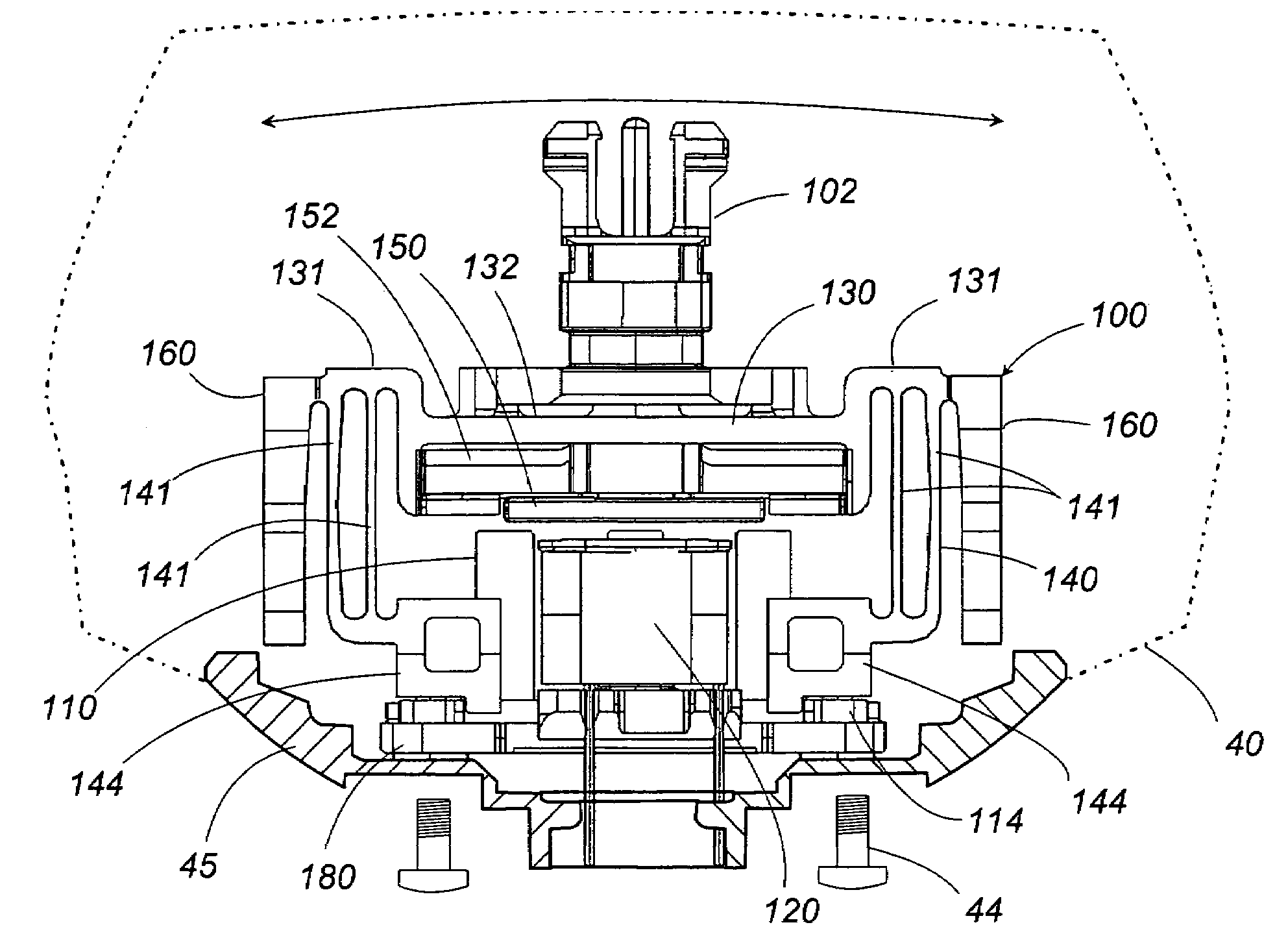
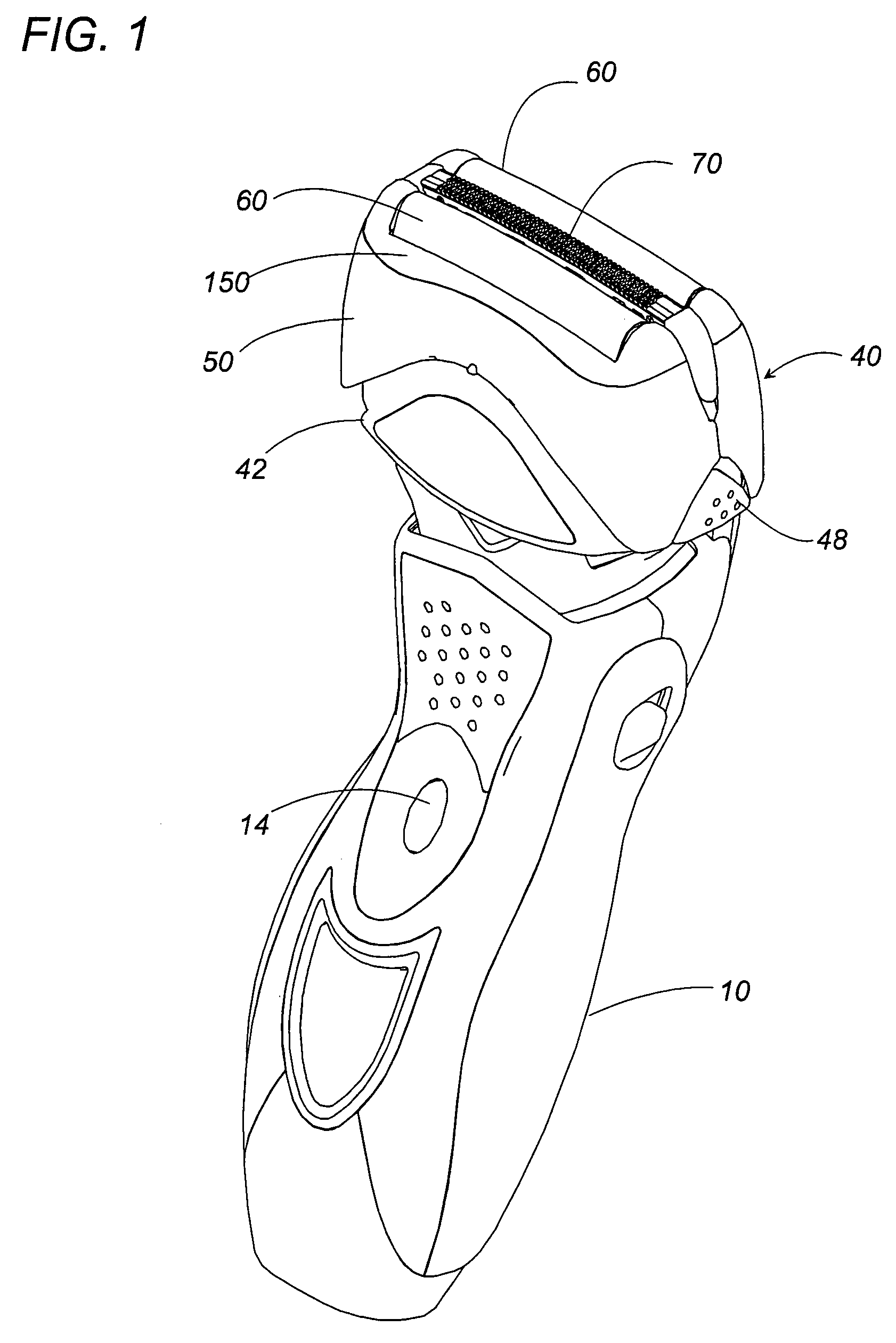
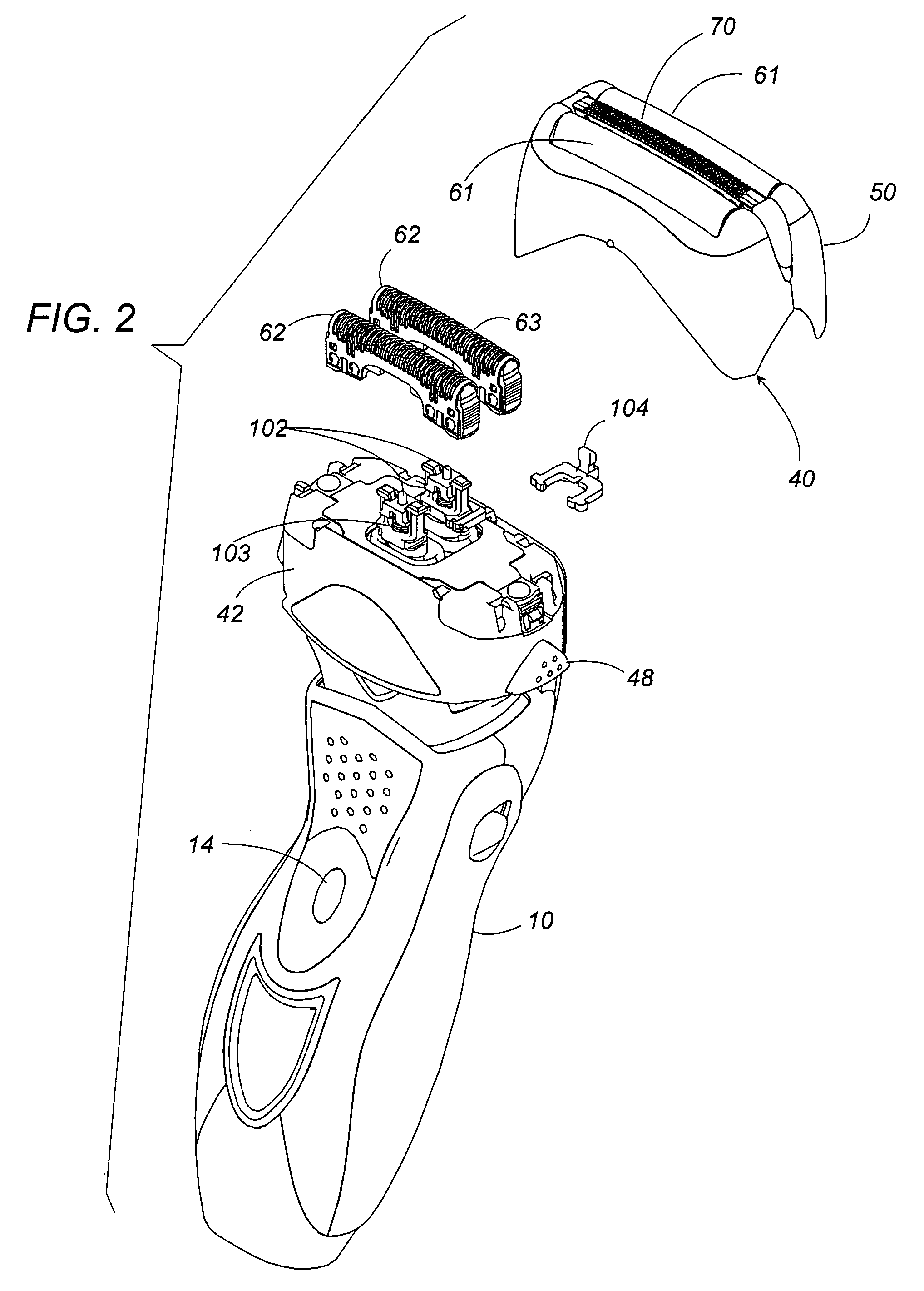
[0019]Referring now to FIGS. 1 to 6, there is shown a dry shaver in accordance with a preferred embodiment of the present invention. The shaver is basically composed of a grip 10 shaped to be grasped by a user' hand, and a shaving head 40 mounted on top of the grip 10 to be swingable relative thereto. The grip 10 accommodates electronic components forming a power supply and a switch actuated by a button 14 on the exterior of the grip 10. The shaving head 40 is supported to the grip through a linkage mechanism 90 by which the shaving head 40 is allowed to swing relative to the grip 10 about a swing axis running in the thickness direction of the shaving head 40.

[0020]The shaving head 40 is elongated to have a lengthwise axis and carries two foil cutter units 60 and a slit cutter unit 70. The foil cutter units 60 are disposed respectively on the front and rear upper ends of the shaver head in parallel relation with each other, while the slit cutter unit 70 is interposed between the foi...


PUM


Abstract

A reciprocatory dry shaver has a shaving head carrying an outer cutter, and an inner cutter. An actuator is mounted in the shaving head for driving the inner cutter. The actuator includes an oscillator which carries a joint for driving connection to the inner cutter. Resilient coupling links are provided to support the oscillator to the shaving head in order to allow the oscillator to reciprocate relative to the shaving head. The resilient coupling link has its upper end coupled to the oscillator and has its lower end which is farther away from the inner cutter than the oscillator and is anchored to the shaving head. Thus, the oscillator is supported as being floated or lifted with respect to the shaving head, thereby being allowed to travel along a path which is somewhat arcuate in coincidence with the arc of the outer cutter.

Description

TECHNICAL FIELD[0001]The present invention is directed to a reciprocatory dry shaver with an arcuately curved outer cutter.BACKGROUND ART[0002]Japanese Utility Model Publication No. 05-48870 discloses a reciprocatory dry shaver having an outer cutter which is curved arcuately along its length. The shaver has a shaving head with an actuator for driving an inner cutter along the length of the outer cutter for shearing hairs therebetween. The actuator includes an oscillator provided with a joint for connection with the inner cutter. The oscillator is supported to the shaving head by means of resilient coupling link which allows the oscillator to move in relation to the shaving head for driving the inner cutter. The resilient coupling link extends from each of the opposite ends oscillator and is fixed to shaving head at a point closer to the inner cutter than the oscillator such that the oscillator is suspended from that point within the shaving head. Consequently, thus suspended oscill...

Claims


Application Information

Patent Timeline
Patent Type & Authority Patents(United States)
IPC IPC(8): B26B19/02
CPCB26B19/04B26B19/282B26B19/02
Inventor SHIBA, TAKESHIMOTOHASHI, RYOYABUUCHI, HIDEKAZUSHIMIZU, HIROAKI
Owner MATSUSHITA ELECTRIC WORKS LTD
Why Eureka
Try Eureka