
Emery wheel grinding machine with adjustable drill bit chuck

a technology of adjustable chuck and grinding machine, which is applied in the direction of edge grinding machine, twisting drill, manufacturing tools, etc., can solve the problems of degrading the effect of finishing drill bit, inapplicability to a particular drill or cutter with two or more blades, and serious improvemen

Active Publication Date: 2009-02-10
TAIWAN MORE CASH VILLAGE
View PDF3 Cites 5 Cited by
  • Summary
  • Abstract
  • Description
  • Claims
  • Application Information

AI Technical Summary

Benefits of technology

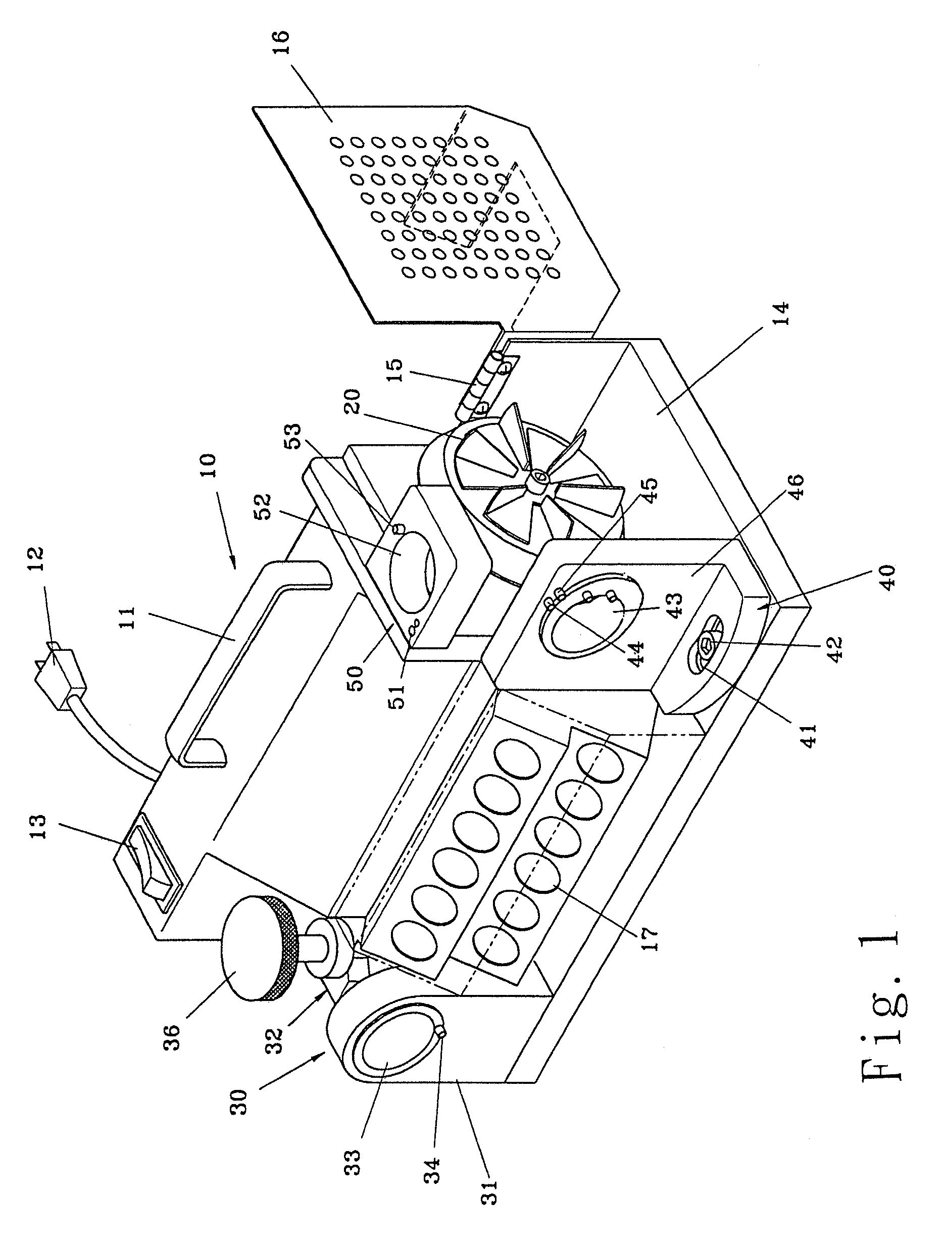
"The present invention is an emery wheel grinding machine with an adjustable bit chuck that has a tilted T-bushing. The machine has several stop traps that correspond to the number of blades on the bushing, and two stop pins to define the turning angle of the hobbing cutter. The tilted T-bushing can adjust the chuck angle based on the blades' figure and number, and also control the turning angle of the hobbing cutter with the stop pins to effectively shave the clearance angles and recesses between the blades. The technical effects of the invention include improved grinding efficiency and accuracy."

Problems solved by technology

With the grinding machine described above, the grinding or shaving effect can only reach to the very small part surrounding the central pointed drill head without reaching further to the portion of the blade edge at the recessed clearance, that greatly degrades the effect of finishing drill bit.
However, the improved portable grinding machine patented by No. 547,228 described above is still having a limited use for grinding conventional drill or cutter only, it is inapplicable to a particular drill or cutter with two or more blades.
For these defects noticeable on the prior art, further improvement is seriously required.

Method used


Image

  • Emery wheel grinding machine with adjustable drill bit chuck
  • Emery wheel grinding machine with adjustable drill bit chuck
  • Emery wheel grinding machine with adjustable drill bit chuck

Examples


Embodiment Construction

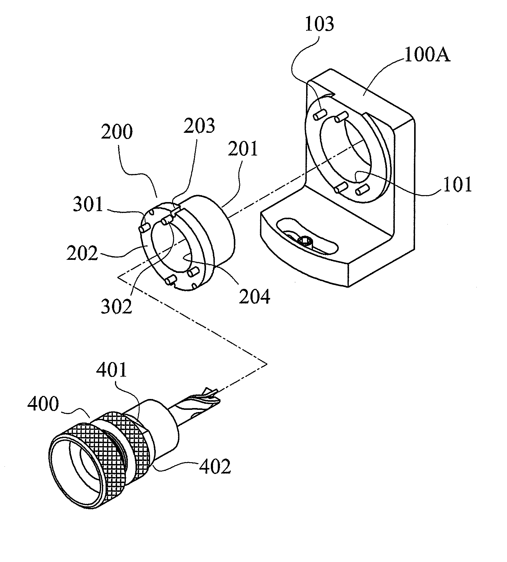
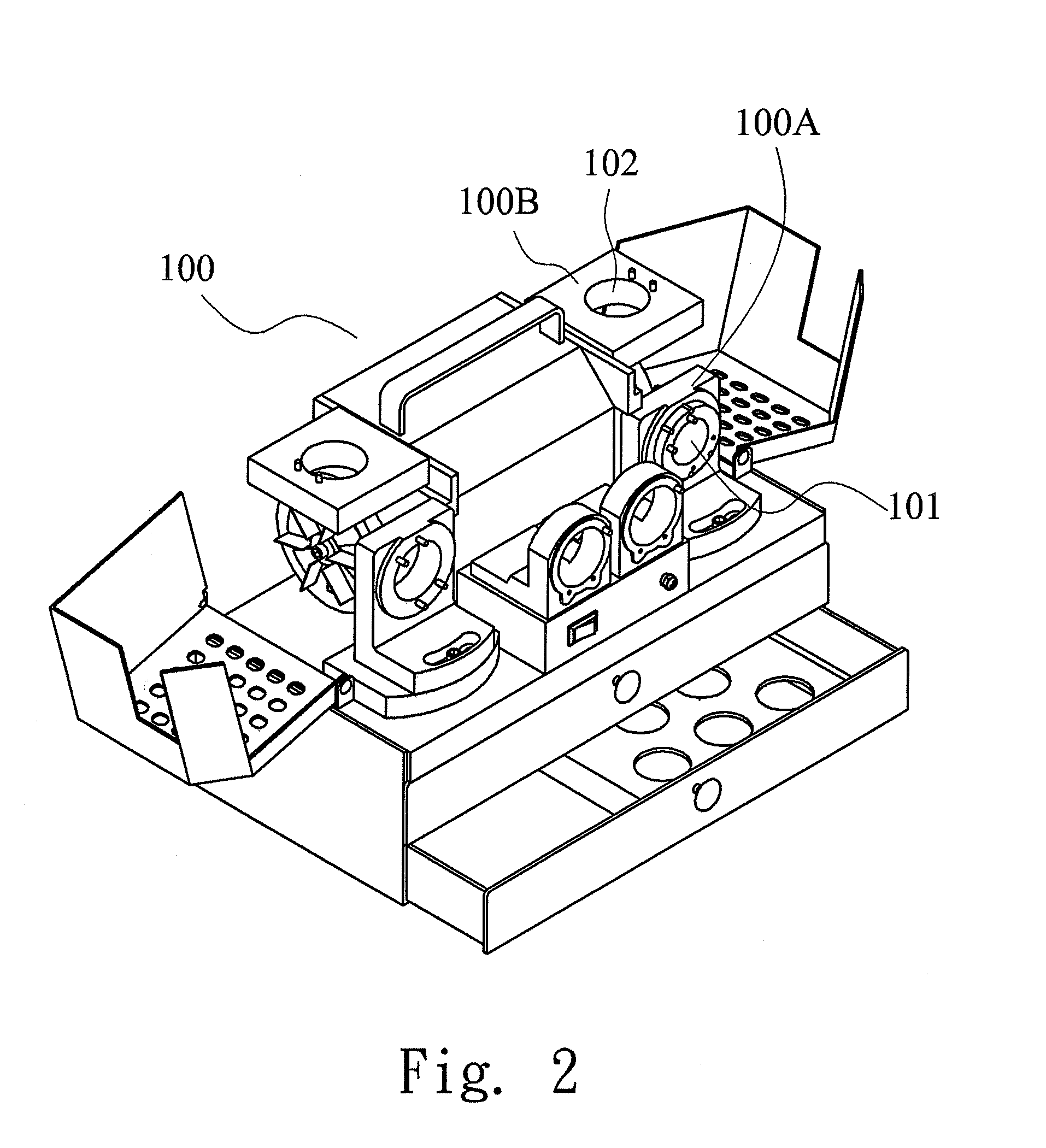
[0025]Referring to FIG. 2 and FIG. 3, the adjustable drill bit chuck of the present invention which accommodates a grinder 100, is provided with a first drill chuck 100A and a second drill chuck 100B. The former has a containment hole 101, and the latter has a T-bushing 200 with a containment hole 102 respectively. One end 201 of the T-bushing 200 can be inserted into the containment hole 101, while the other end has a larger outer diameter such that an outer flange 202 is emerged out of the containment hole 101 after insertion. Two, three, or four pairs of stop traps 203 are provided along the circumference of the outer flange 202 according to the number of blades of the drill or hobbing cutter to be shaved. The stop traps 203 can be engaged with corresponding clamp studs 103 which are provided on the outer surface of the drill chuck so as to hold the T-bushing 200 in place in the containment hole 101 of the drill chuck.

[0026]Referring to FIG. 4, the T-bushing 200 has a tapered hol...


PUM

PropertyMeasurementUnit
angleaaaaaaaaaa
circumferenceaaaaaaaaaa
turning angleaaaaaaaaaa

Abstract

The emery wheel grinding machine with adjustable drill bit chuck disclosed herein has an adjustable chuck in which is provided with a T-bushing having an outer flange formed at one end thereof. The outer flange is provided with several pairs of stop traps along its circumference, whereas the number of stop traps are determined according to the number of cutter blades to be shaved. Several stop pins are formed on the surface of the outer flange to control the turning angle of the drill bit or the cutter. The T-bushing further has a taper hole in it. When the chuck head which holds the drill bit or the cutter is inserted into the taper hole, the cutter blade can be in contact with the emery wheel with a certain tilted angle thereby allowing the cutter blades of various length and number to be effectively shaved, ground and finished.

Description

BACKGROUND OF THE INVENTION[0001]1. Field of the Invention[0002]The present invention relates to emery wheel grinding machine with an adjustable chuck, and more particularly, to an emery wheel grinding machine equipped with an adjustable drill bit chuck suitable for shaving the drill bit or a cutter of a two or more faced and variously lengthed blade of a hobbing cutter other than a single blade one.[0003]2. Description of the Related Art[0004]A conventional portable grinding machine, as it was disclosed and published by Taiwan Pat. No. 286610, 155338, is composed of a housing, a cap covered at one end thereof, a transmission gearing equipped in the housing, a emery wheel and guiding members. When it is to be used, the whole unit is set on an electric motor with the grinding machine coupled with the main shaft of the electrical drill so as to impart the rotational power of the electrical drill to the emery wheel with transmission gearing for running. At the same time, a drill bit or...

Claims


Application Information

Patent Timeline
Patent Type & Authority Patents(United States)
IPC IPC(8): B24B9/00
CPCB24B3/26
Inventor LIAO, MING-KO
Owner TAIWAN MORE CASH VILLAGE
Learn More