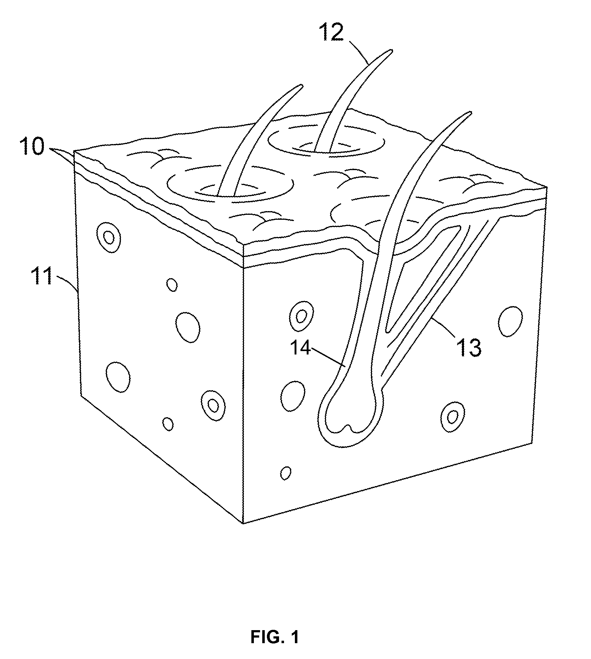
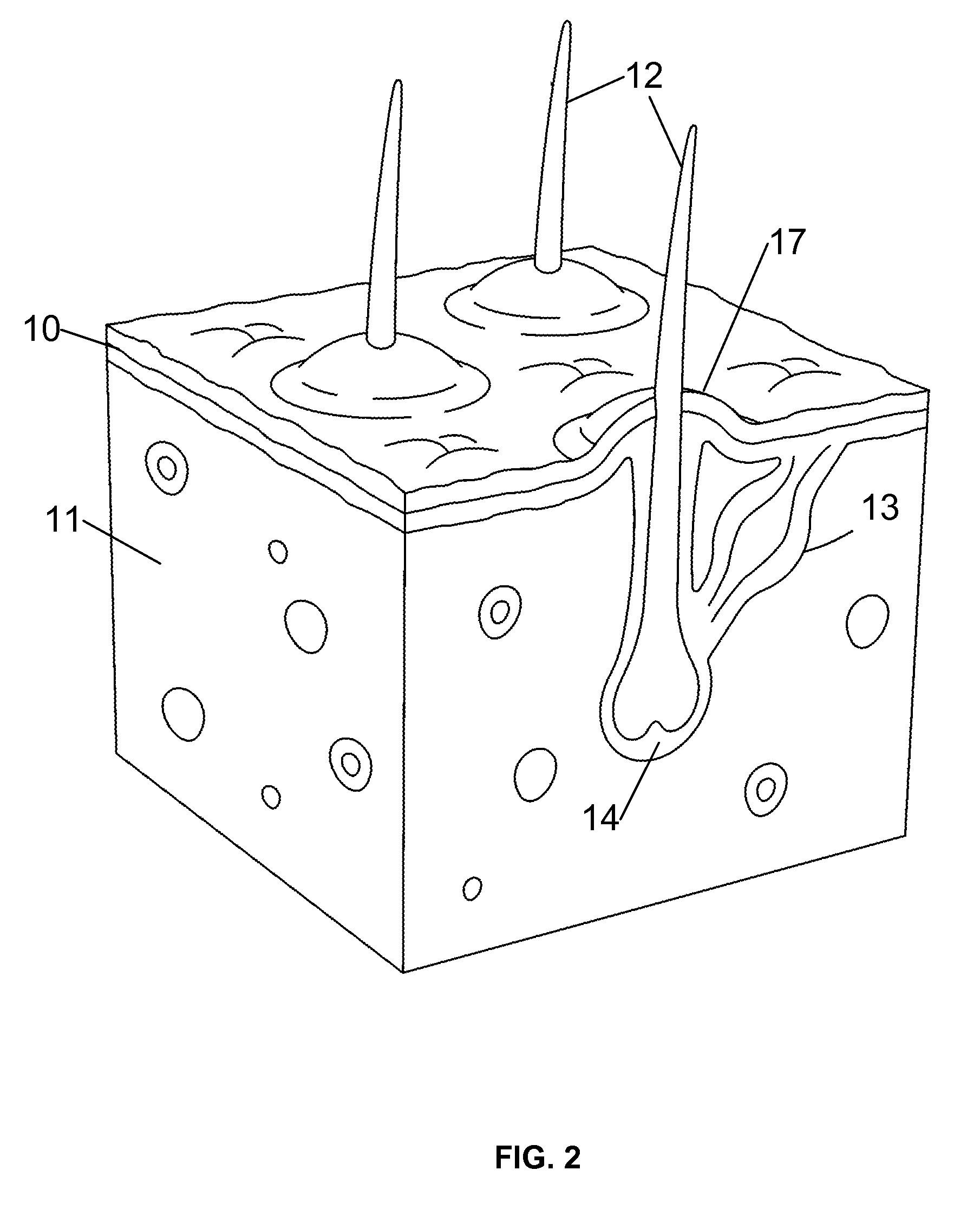
Pilomotor effect stimulating device and method
a stimulating device and pedal motor technology, applied in the field of pedal motor effect stimulating devices and methods, can solve the problems of increasing the risk of skin damage or irritation, and achieve the effect of more effective shaving
- Summary
- Abstract
- Description
- Claims
- Application Information
AI Technical Summary
Benefits of technology
Problems solved by technology
Method used
Image
Examples
first embodiment
[0026]FIGS. 3 to 5 illustrate a hand held electronic device 20 designed to stimulate the pilomotor effect in human skin. As discussed above, this embodiment is designed as a shaving aid. Device 20 has a handle 22 and a head 24 having a lower face 25 configured to run over the skin. One or more shaving blades 26 are mounted in the head to project from face 25, along with two or more electrodes or probes 28 which are positioned in front of the blades to contact the skin in advance of the blades 26 as the shaving head is run over an area to be shaved. Three electrodes are illustrated in FIG. 5, but two or more than three electrodes may be used in other embodiments, with at least one positive and one negative electrode, or multiple positive or negative electrodes.
[0027]Handle 22 provides an enclosure for electronic control unit 30 and power supply or batteries 32, as illustrated in FIG. 4 where a removable cover 34 of the handle is removed to reveal the control unit. The modules and com...
second embodiment
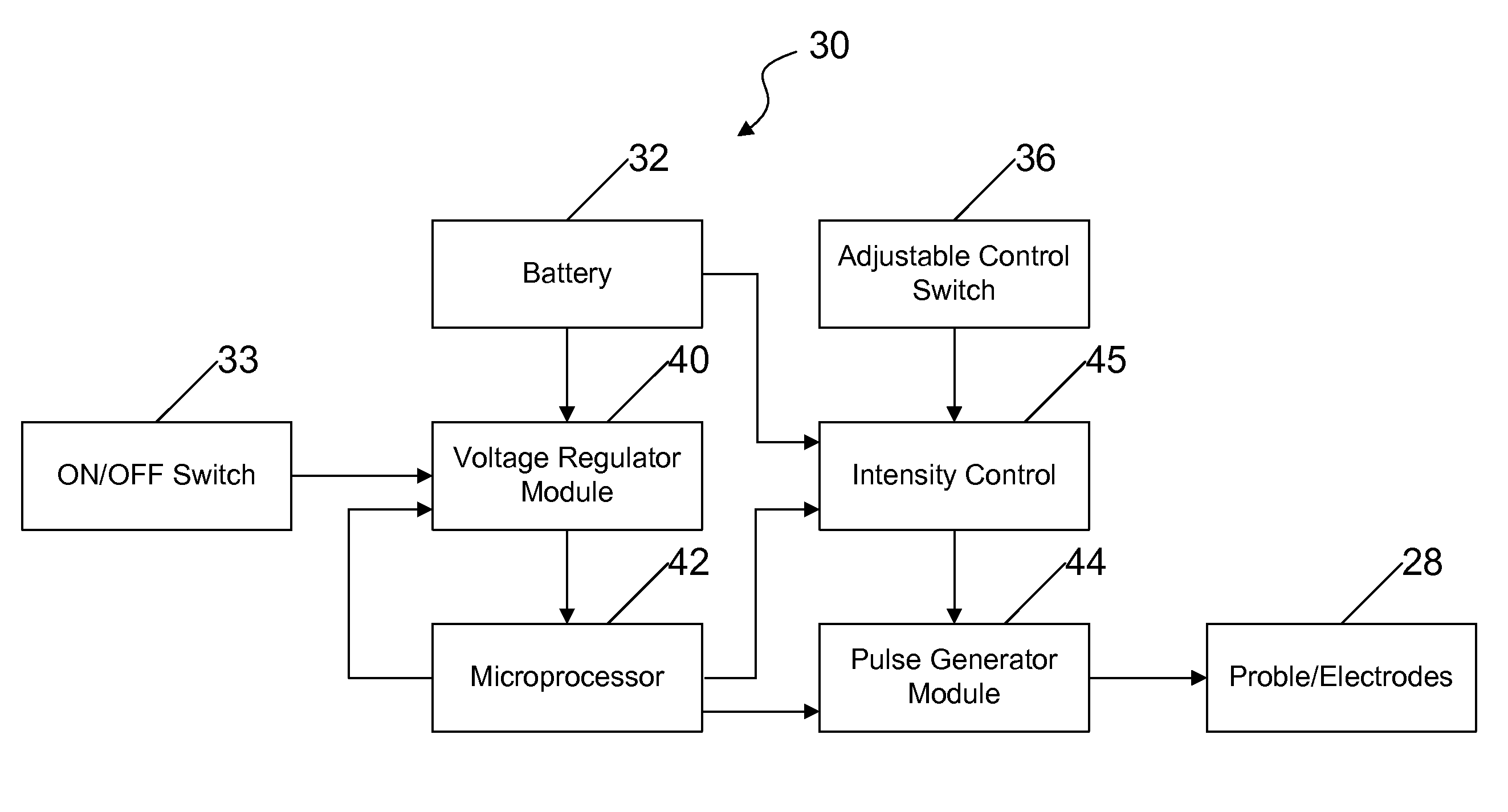
[0028]FIG. 6 illustrates a pilomotor effect stimulating device 50 which is similar to that of FIGS. 3 to 5 and has the same electronic control unit 30 and power supply as the previous embodiment, but which has no shaving blade or blades and may be used either as a shaving aid or for other purposes. As in the previous embodiment, device 50 has a handle 52 and a head 54 which carries a plurality of probes or electrodes 28 on its lower surface 56, but no blades. The electronic control unit 30 is enclosed in handle 52 and connected to electrodes 28. The power supply and the control unit are accessible via removable cover 34, as in the embodiment of FIGS. 3 to 5. Although not visible in FIG. 6, the device 50 has the same on-off button 35 and adjustable power control switch 38 as illustrated in FIGS. 3 and 4 for the previous embodiment, and the handle 52 is substantially identical to handle 22.
[0029]FIG. 7 is a functional block diagram illustrating the basic components of one embodiment ...
PUM
| Property | Measurement | Unit |
|---|---|---|
| frequency F2 | aaaaa | aaaaa |
| voltage | aaaaa | aaaaa |
| frequency F2 | aaaaa | aaaaa |
Abstract
Description
Claims
Application Information
 - R&D
- Intellectual Property
- Life Sciences
- Materials
- Tech Scout
- Unparalleled Data Quality
- Higher Quality Content
- 60% Fewer Hallucinations
Browse by: Latest US Patents, China's latest patents, Technical Efficacy Thesaurus, Application Domain, Technology Topic, Popular Technical Reports.
© 2025 PatSnap. All rights reserved.Legal|Privacy policy|Modern Slavery Act Transparency Statement|Sitemap|About US| Contact US: help@patsnap.com


