Gas turbine heat exchanger assembly and method for fabricating same

a heat exchanger and gas turbine technology, applied in the field of gas turbine engines, can solve the problems of increasing specific fuel consumption, increasing the total pressure loss of hot exhaust gas on the gas side, and unfavorable regenerative engine systems for aircraft applications, and achieve the effect of facilitating the discharge of air from the compressor

Active Publication Date: 2008-02-26
GENERAL ELECTRIC CO
View PDF10 Cites 17 Cited by
  • Summary
  • Abstract
  • Description
  • Claims
  • Application Information

AI Technical Summary

Benefits of technology

[0007]In another aspect, a heat exchanger assembly for a gas turbine engine is provided. The heat exchanger assembly includes an annular heat exchanger coupled in flow communication to a compressor. The heat exchanger includes a first manifold comprising an inlet and an outlet, wherein the manifold inlet comprises a cross-sectional area that is inversely proportional to a cross-sectional area of the manifold outlet, a first quantity of heat exchanger elements coupled in flow communication with the manifold inlet, a second quantity of heat exchanger elements coupled in flow communication with the manifold outlet, and a plurality of channels coupled in flow communication with the first and second quantity of heat exchanger elements to facilitate channeling compressor discharge air from the first quantity of heat exchanger elements to the second quantity of heat exchanger elements.
[0008]In a further aspect, a gas turbine engine is provided. The gas turbine engine includes a compressor, a combustor downstream from the compressor, a turbine coupled in flow communication with the combustor, and a heat exchanger assembly. The heat exchanger assembly includes an annular heat exchanger coupled in flow communication to a compressor. The heat exchanger includes a first manifold comprising an inlet and an outlet, wherein the manifold inlet comprises a cross-sectional area that is inversely proportional to a cross-sectional area of the manifold outlet, a first quantity of heat exchanger elements coupled in flow communication with the manifold inlet, a second quantity of heat exchanger elements coupled in flow communication with the manifold outlet, and a plurality of channels coupled in flow communication with the first and second quantity of heat exchanger elements to facilitate channeling compressor discharge air from the first quantity of heat exchanger elements to the second quantity of heat exchanger elements.

Problems solved by technology

However, since known heat exchangers are typically physically large and rectangular-shaped, such heat exchangers are mounted externally to the gas turbine engine.
The resulting large and irregular heat exchanger assembly, coupled with the added weight and cost of the heat exchanger and ducting, generally makes regenerative engine systems unfeasible for aircraft applications.
In addition, although recuperated engines generally achieve a better low power specific fuel consumption than other known gas turbine engines, when such engines are operated with a heat exchanger assembly and at a higher operating power, gas-side total pressure losses of the hot exhaust gas stream may be relatively high through the exhaust system heat exchanger.
The increased gas-side pressure losses caused by the heat exchanger assembly may result in an increased specific fuel consumption.
Moreover, since the size of the heat exchanger is generally desired to be as small as possible, less space is available for a bypass system, which may result in high exhaust total pressure losses during high-power engine operating conditions.

Method used


Image

  • Gas turbine heat exchanger assembly and method for fabricating same
  • Gas turbine heat exchanger assembly and method for fabricating same
  • Gas turbine heat exchanger assembly and method for fabricating same

Examples


Embodiment Construction

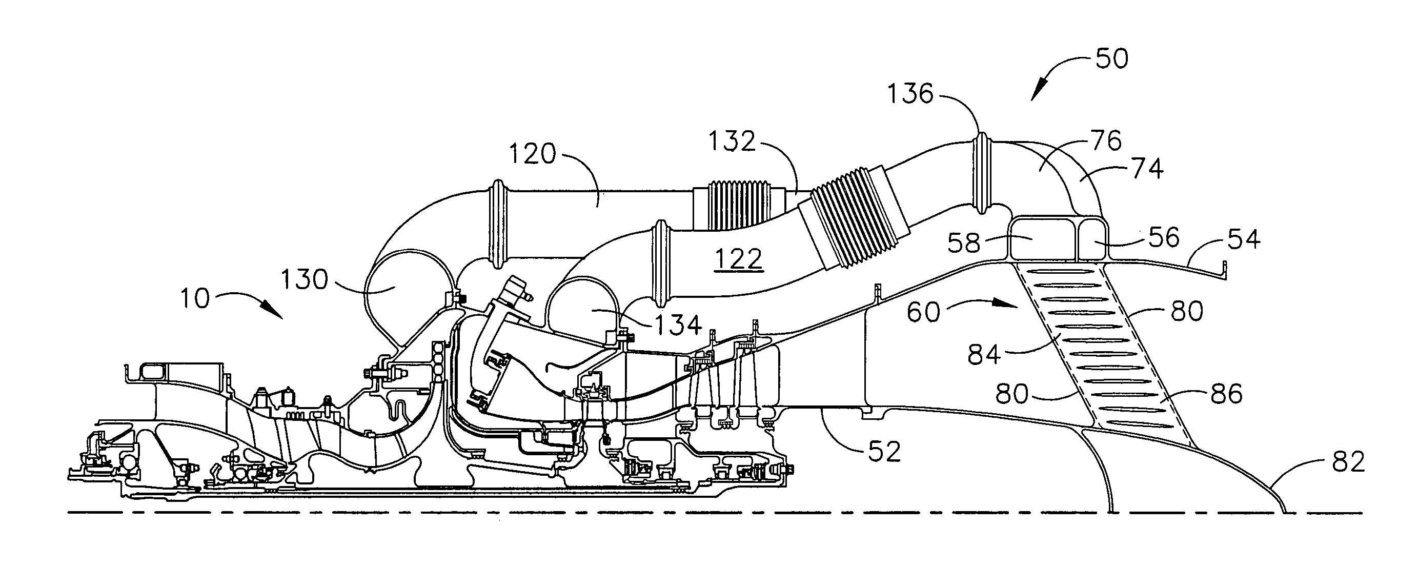
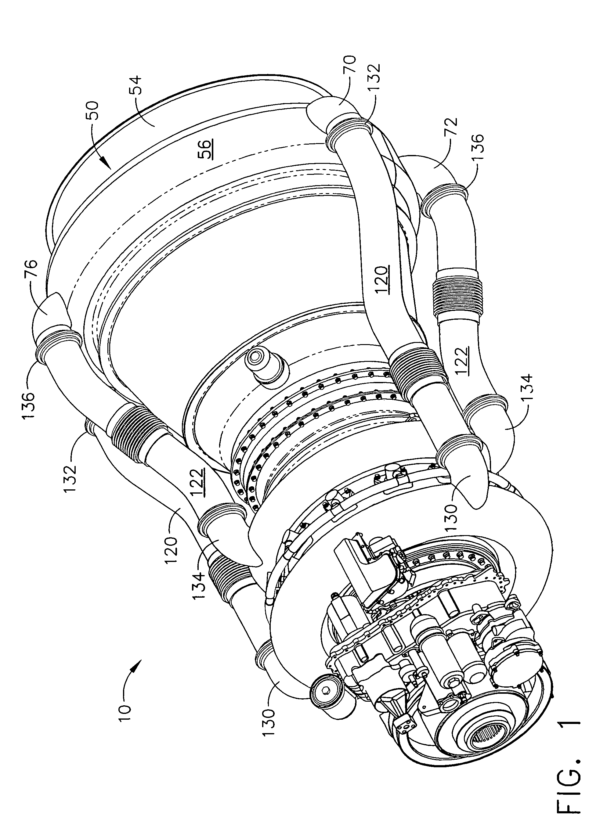
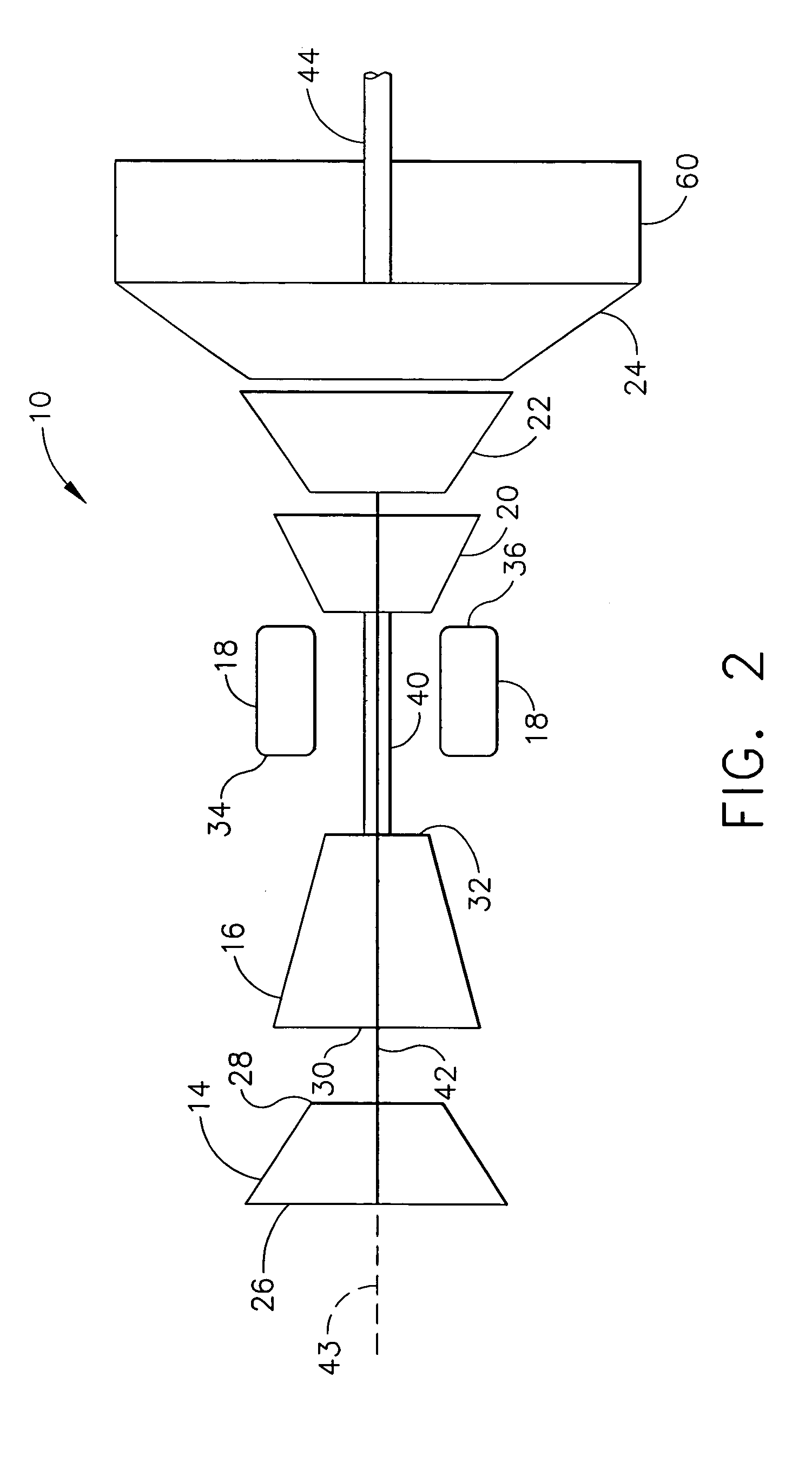
[0016]FIG. 1 is a perspective view of an exemplary gas turbine engine 10 including a heat exchanger assembly 50. FIG. 2 is a block diagram of gas turbine engine 10 (shown in FIG. 1). Gas turbine engine 10 includes, in serial flow relationship, a low pressure compressor or booster 14, a high pressure compressor 16, a combustor 18, a high pressure turbine 20, a low pressure, or intermediate turbine 22, and a power turbine or free turbine 24. Low pressure compressor or booster 14 has an inlet 26 and an outlet 28, and high pressure compressor 16 includes an inlet 30 and an outlet 32. Combustor 18 has an inlet 34 that is substantially coincident with high pressure compressor outlet 32, and an outlet 36. In one embodiment, combustor 18 is an annular combustor. In another embodiment, combustor 18 is a dry low emissions (DLE) combustor.

[0017]High pressure turbine 20 is coupled to high pressure compressor 16 with a first rotor shaft 40, and low pressure turbine 22 is coupled to low pressure ...


PUM


Abstract

A method for assembling a gas turbine engine includes fabricating a heat exchanger that includes a first manifold including an inlet and an outlet, a first quantity of heat exchanger elements coupled in flow communication with the manifold inlet, a second quantity of heat exchanger elements coupled in flow communication with the manifold outlet, and a plurality of channels coupled in flow communication with the first and second quantity of heat exchanger elements to facilitate channeling compressor discharge air from the first quantity of heat exchanger elements to the second quantity of heat exchanger elements, and coupling the heat exchanger assembly to the gas turbine engine such that the heat exchanger is positioned substantially concentrically with respect to a gas turbine engine axis of rotation, and such that the heat exchanger is configured to receive compressor discharge air and channel the compressor discharge air to the combustor.

Description

CROSS REFERENCE TO RELATED APPLICATIONS[0001]This application is a Continuation In Part of U.S. patent application Ser. No. 10 / 828,663 filed Apr. 21, 2004 now U.S. Pat. No. 7,254,937.BACKGROUND OF THE INVENTION[0002]This invention relates generally to gas turbine engines, and more particularly to heat exchangers used with gas turbine engines.[0003]At least one known gas turbine engine uses a heat exchanger, generally referred to as a recuperator, to facilitate reducing specific fuel consumption. More specifically, pressurized air from the compressor section of the gas turbine engine is channeled from the gas turbine engine, and through the heat exchanger, such that the hot exhaust gases of the engine raise the operating temperature of the pressurized air prior to it being supplied into the combustor.[0004]Known heat exchanger assemblies are positioned between the gas turbine engine exhaust gas box and the exhaust stack. At least some known heat exchanger assemblies include a pair of...

Claims


Application Information

Patent Timeline
Patent Type & Authority Patents(United States)
IPC IPC(8): F02C7/10F02C7/08F28D7/00
CPCF02C7/08F28D7/0058F28D21/0003
Inventor VANDERMOLEN, ROBERT
Owner GENERAL ELECTRIC CO
Why Eureka
Try Eureka