Igniter tube and method of assembling same

a technology of igniter tubes and igniters, which is applied in the direction of burner ignition devices, turbine/propulsion engine ignition, lighting and heating apparatus, etc., can solve the problems of high temperature, temperature gradient, and/or stress, and the downstream side of the igniters and their respective igniter tubes are not as effectively cooled, and can damage the thermal stress of the combustor

Active Publication Date: 2009-06-16
GENERAL ELECTRIC CO
View PDF11 Cites 30 Cited by
  • Summary
  • Abstract
  • Description
  • Claims
  • Application Information

AI Technical Summary

Benefits of technology

[0006]In a first aspect, a method for assembling a gas turbine engine igniter tube assembly is provided. The gas turbine engine includes a combustor, and at least one igniter inserted at least partially into the combustor. The method includes providing an igniter tube as assembly including an axis of symmetry extending therethrough, an igniter tube, and a ferrule, the igniter tube having a first opening extending coaxially therethrough having a diameter sized to receive a portion of the igniter therethrough such that the igniter tube circumscribes the igniter and such that a gap is defined between the igniter tube and the igniter, and a plurality of cooling air openings extending through at least one of the igniter tube and the ferrule to facilitate channeling cooling air into the gap, and coupling the igniter tube and the ferrule to the combustor.
[0007]In another aspect, an igniter tube assembly for a gas turbine engine is provided. The gas turbine engine includes a combustor, and at least one igniter inserted at least partially into the combustor. The igniter tube assembly includes an axis of symmetry extending therethrough, an igniter tube that includes a first opening extending coaxially therethrough having a diameter sized to receive a portion of the igniter therethrough such that the igniter tube circumscribes the igniter and such that a gap is defined between the igniter tube and the igniter, a ferrule coupled to the igniter tube, and a plurality of cooling air openings extending through at least one of the igniter tube and the ferrule to facilitate channeling cooling air into the gap.

Problems solved by technology

As a result, a downstream side of the igniters and their respective igniter tubes are not as effectively cooled as an upstream side of the igniters and their respective igniter tubes which are each cooled using airflow that has not separated.
Additionally, hot gases ingested into the igniter tube may result in relatively high temperatures, and temperature gradients, and / or stresses.
Over time, continued operation with increased temperature gradients may induce potentially damaging thermal stresses into the combustor that exceed an ultimate strength of materials used in fabricating the igniter tubes.
As a result, thermally induced transient and steady state stresses may cause low cycle fatigue (LCF) failure of the igniter tubes.
Because igniter tube replacement is a costly and time-consuming process, at least some known combustors increase a gap between the igniters and the igniter tubes to facilitate reducing thermal circumferential stresses induced within the igniter tubes.
However, because such air is used in the combustion process, such gaps provide only intermittent cooling, and the igniter tubes may still require replacement.

Method used


Image

  • Igniter tube and method of assembling same
  • Igniter tube and method of assembling same
  • Igniter tube and method of assembling same

Examples


Embodiment Construction

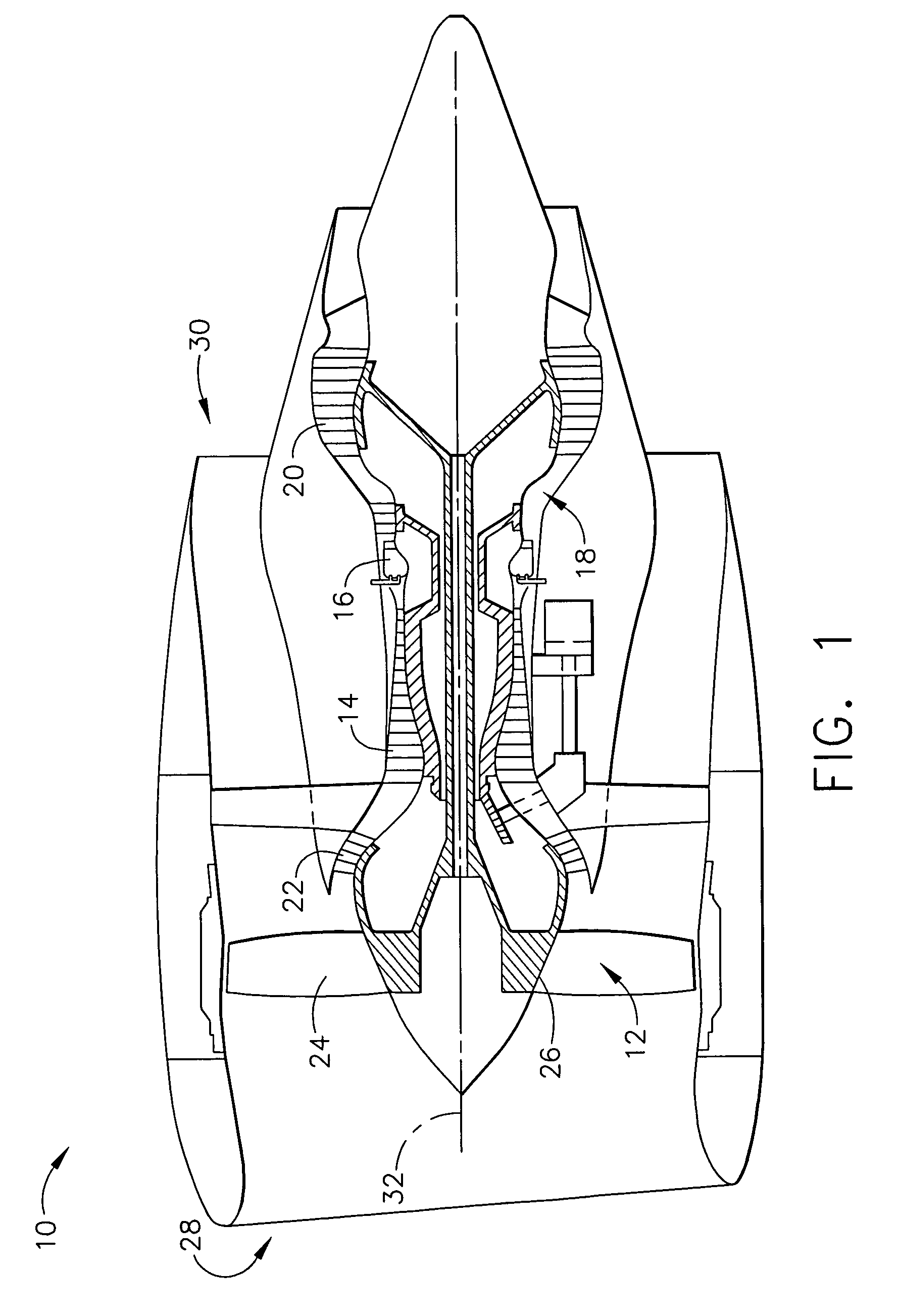
[0015]FIG. 1 is a schematic illustration of a gas turbine engine 10 including a fan assembly 12, a high pressure compressor 14, and a combustor 16. Engine 10 also includes a high pressure turbine 18, a low pressure turbine 20, and a booster 22. Fan assembly 12 includes an array of fan blades 24 extending radially outward from a rotor disc 26. Engine 10 has an intake side 28 and an exhaust side 30. In one embodiment, gas turbine engine 10 is a GE90 engine commercially available from General Electric Company, Cincinnati, Ohio.

[0016]In operation, air flows along an engine rotation axis 32 through fan assembly 12 and compressed air is supplied to high pressure compressor 14. The highly compressed air is delivered to combustor 16. Airflow from combustor 16 drives turbines 18 and 20, and turbine 20 drives fan assembly 12.

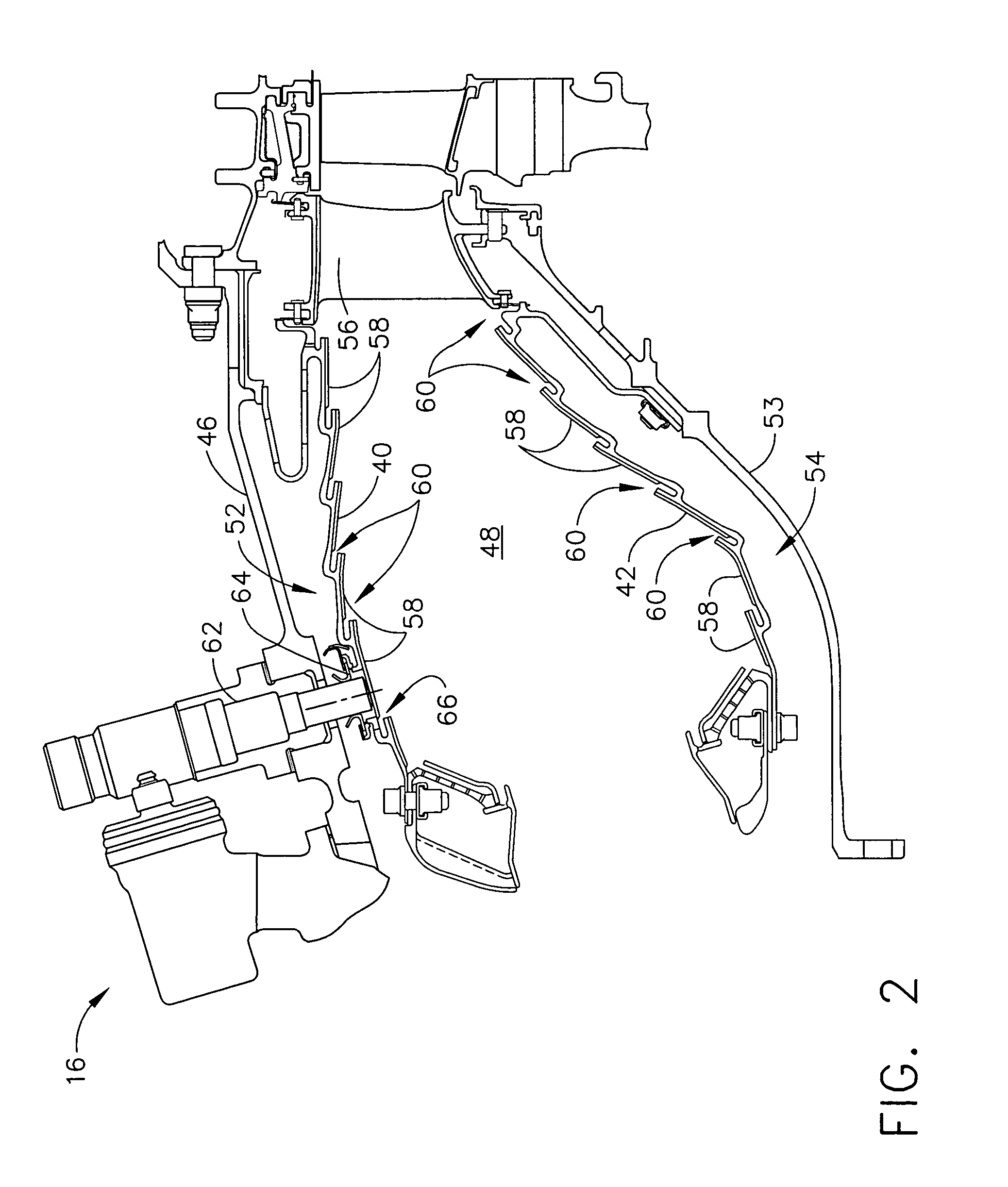
[0017]FIG. 2 is a cross-sectional view of combustor 16 used in gas turbine engine 10. Combustor 16 includes an annular outer liner 40, an annular inner liner 42, and a do...


PUM


Abstract

An igniter tube assembly includes an axis of symmetry extending therethrough, an igniter tube that includes a first opening extending coaxially therethrough having a diameter sized to receive a portion of the igniter therethrough such that the igniter tube circumscribes the igniter and such that a gap is defined between the igniter tube and the igniter, a ferrule coupled to the igniter tube, and a plurality of cooling air openings extending through at least one of the igniter tube and the ferrule to facilitate channeling cooling air into the gap.

Description

BACKGROUND OF THE INVENTION[0001]This invention relates generally to gas turbine engines, and more specifically to igniter tubes used with gas turbine engine combustors.[0002]Combustors are used to ignite fuel and air mixtures in gas turbine engines. Known combustors include at least one dome attached to a combustor liner that defines a combustion zone. More specifically, the combustor liner includes an inner and an outer liner that extend from the dome to a turbine nozzle. The liner is spaced radially inwardly from a combustor casing such that an inner and an outer passageway are defined between the respective inner and outer liner and the combustor casing.[0003]At least some known gas turbine engines include an igniter tube that facilitates maintaining the igniter in alignment within the combustor. More specifically, the igniter extends through the igniter tube such that the igniter is maintained in alignment relative to the combustion chamber.[0004]During operation, high pressure...

Claims


Application Information

Patent Timeline
Patent Type & Authority Patents(United States)
IPC IPC(8): F02C7/26F02C7/264
CPCF23R3/06F23D2207/00F23D2900/00014F23R2900/00005F23R2900/03044
Inventor HOLLAND, THOMAS GEORGEVISE, STEVEN CLAYTONMCMASTERS, MARIE ANN
Owner GENERAL ELECTRIC CO
Why Eureka
Try Eureka