
Structures for supporting vibrators and devices for measuring physical quantities

a technology for vibrators and structures, applied in the direction of turn-sensitive devices, instruments, device material selection, etc., can solve problems such as substantial temperature drift, and achieve the effect of reducing zero-point temperature dri

Active Publication Date: 2008-02-26
SEIKO EPSON CORP
View PDF7 Cites 7 Cited by
  • Summary
  • Abstract
  • Description
  • Claims
  • Application Information

AI Technical Summary

Benefits of technology

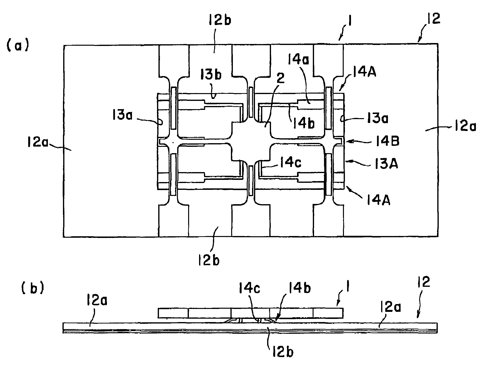
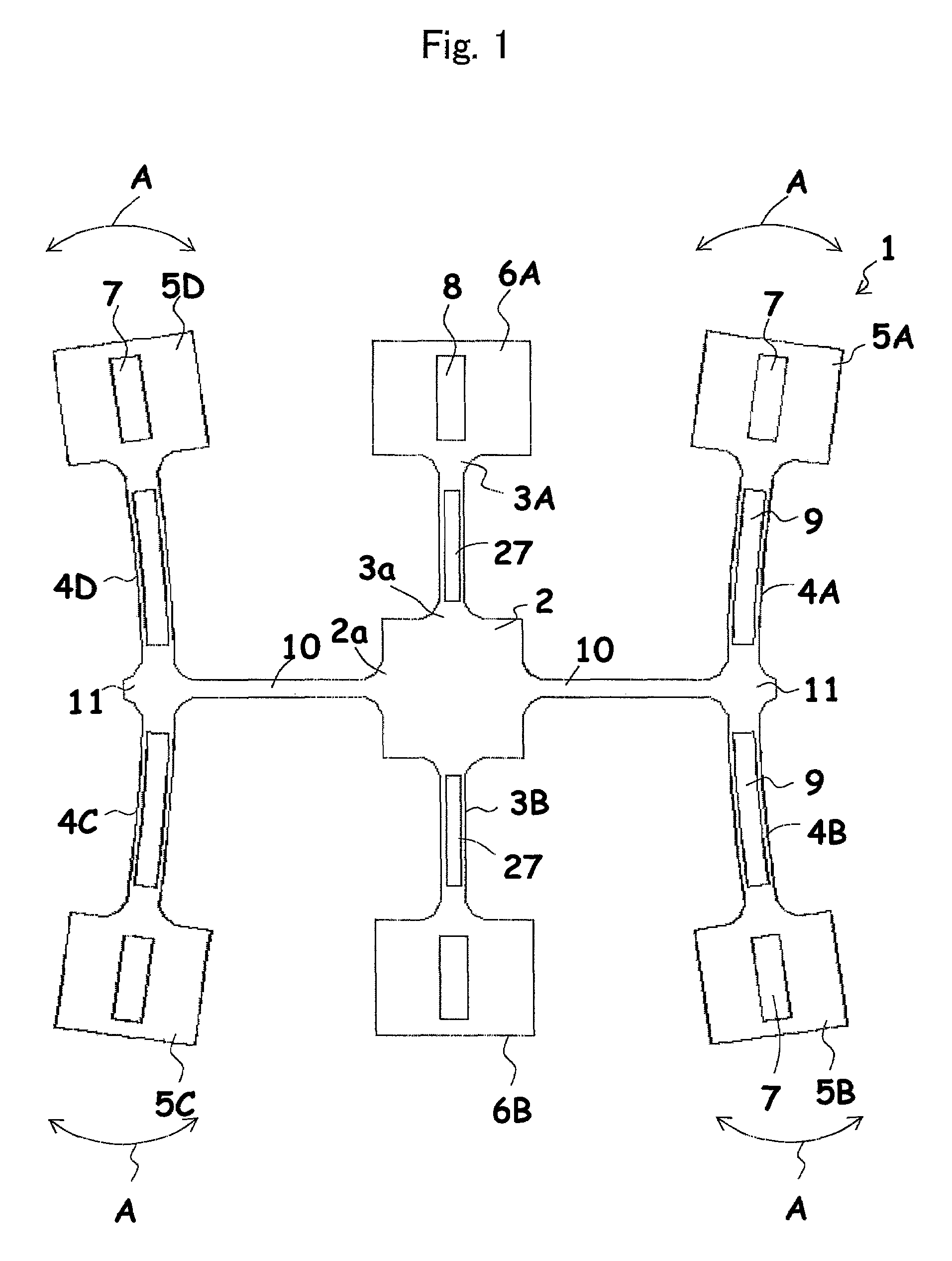
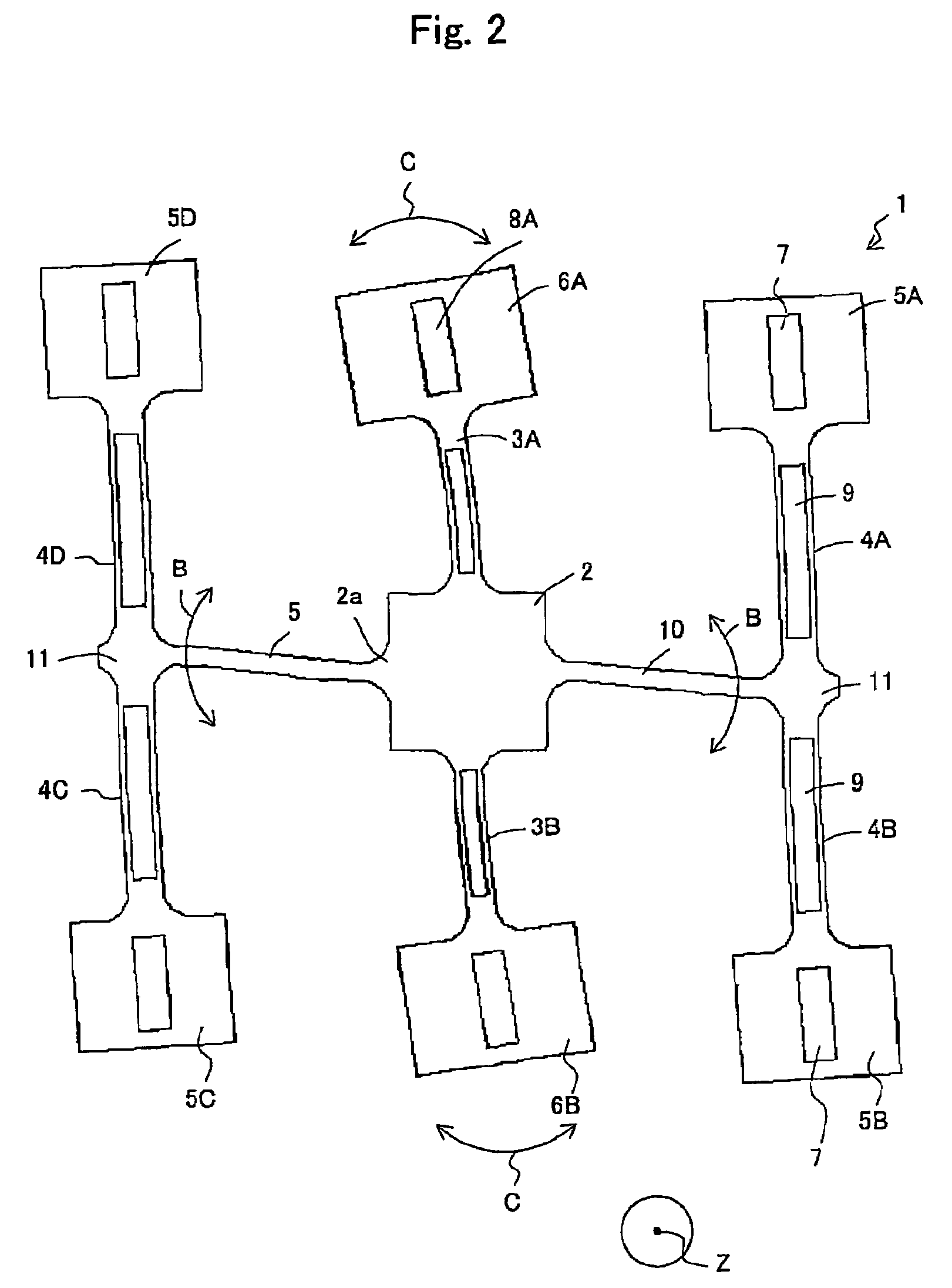
The present invention provides a structure for supporting a vibrator to reduce the zero point temperature drift of the detection signal. The structure includes a substrate and a bonding wire fixed to the substrate and connected with the vibrator. The vibrator is supported with the bonding wire so that the vibrator is not directly contacted with the substrate. The invention also provides a device for measuring a physical quantity including the supporting structure. The inventors have found that the characteristic vibration frequency of the bonding wire may be very close to the half of the resonance frequency of the driving vibration mode, which may cause resonance of the bonding wire and result in the zero point temperature drift of the vibratory gyroscope. The invention addresses this issue by appropriately changing the form of the bonding wire so that the characteristic vibration frequency is made distant by a specific ratio from the half of the resonance frequency of the driving vibration mode.

Problems solved by technology

According to such supporting methods, however, a substantial temperature drift may be observed, for example, in a high temperature region.

Method used


Image

  • Structures for supporting vibrators and devices for measuring physical quantities
  • Structures for supporting vibrators and devices for measuring physical quantities
  • Structures for supporting vibrators and devices for measuring physical quantities

Examples


example 1

[0096]The vibrator 1 was supported on the substrate according to the same procedure as the comparative example 1, except that the supporting structure shown in FIG. 17 was applied. The numerical values of “fd” and “fw” were shown in table 1. As a result, the dependency of the zero point gyroscope signal component on temperature was shown in FIG. 4. That is, the zero point gyroscope signal component was gradually lowered substantially according to a linear function between minus 40 to plus 85° C. and a particular zero point temperature drift was not observed.

example 2

[0097]The vibrator 1 was supported on the substrate according to the same procedure as the comparative example 1, except that the supporting structure shown in FIG. 15 was applied The numerical values of “fd” and “fw” were shown in table 1. As a result, a peak of zero point temperature drift was detected in a range of minus 40 to 0° C., as shown in FIG. 22. The temperature drift was considered to be due to resonance of vibration of “2fd”. Further, according to the Example 2, the amount of drift was considerably reduced compared with that of the comparative example, and the detuning frequency was changed substantially according to a linear function with respect to temperature in a range of minus 40 to plus 85° C., as shown in FIG. 20.

example 3

[0098]The vibrator 1 was supported on the substrate according to the same procedure as the comparative example 1, except that the supporting structure shown in FIG. 5 was applied. As a result, a peak of zero point temperature drift was detected as shown in FIG. 23 in a range of 0° C. to 30° C. The temperature drift is considered to be due to resonance of “3fd”. Further, according to the Example 3, the amount of d was considerably reduced compared with that of the comparative example, and the detuning frequency was gradually changed according to a linear function with respect to temperature in a range of minus 40 to plus 85° C., as shown in FIG. 21.


PUM


Abstract

A structure for supporting a vibrator 1 is provided. The structure comprises a substrate 12 and bonding wires 14A, 14B fixed to the substrate 12 and connected with the vibrator 1. The vibrator 1 is supported with the bonding wires so that the vibrator 1 is not directly contacted with the substrate 12. “fd” and “fw” satisfy the following formula (1). “fd” represents a resonance frequency of a driving vibration mode of the vibrator and “fw” represents a characteristic frequency of a vibration mode of the bonding wire at room temperature.(fd / 2)×1.05≦fw, or, fw≦(fd / 2)×0.95.  (1)

Description

[0001]This application claims the benefits of Japanese Patent Applications P2005-207047 filed on Jul. 15, 2005, and P2004-263310 filed on Sep. 10, 2004, the entireties of which are incorporated by reference.BACKGROUND OF THE INVENTION[0002]1. Field of the Invention[0003]The present invention provides a structure for supporting a vibrator and a device for measuring a physical quantity such as a vibratory gyroscope.[0004]2. Related Art Statement[0005]In a vehicle control system, a vibratory gyroscope and its vibrator are subjected to a wide temperature range including high and low temperatures. Such temperature range normally includes minus 40° C. to plus 85° C. and may be wider in applications that operate outside the normal temperature range. Particularly when a vibrator is made of a piezoelectric single crystal, the temperature dependency of the single crystal may affect the stability of the gyroscope.[0006]Japanese patent publication 2003-28648A discloses a member for supporting a...

Claims


Application Information

Patent Timeline
Patent Type & Authority Patents(United States)
IPC IPC(8): G01P9/04G01C19/56G01C19/5628H01L41/08H01L41/18
CPCG01C19/5621G01C19/5628G01C19/56
Inventor HAYASHI, SHIGEKIKIKUCHI, TAKAYUKIKINOSHITA, YUSUKE
Owner SEIKO EPSON CORP
Learn More