

Plugless normally-open connector module
a connector module and normally-open technology, applied in the direction of coupling contact members, coupling device connections, electrical equipment, etc., can solve the problems of solution drawbacks and removal of protection circuits, and achieve the effect of reducing training requirements and being easy and inexpensive to fabrica
- Summary
- Abstract
- Description
- Claims
- Application Information
AI Technical Summary
Benefits of technology
Problems solved by technology
Method used
Image

Examples
Embodiment Construction
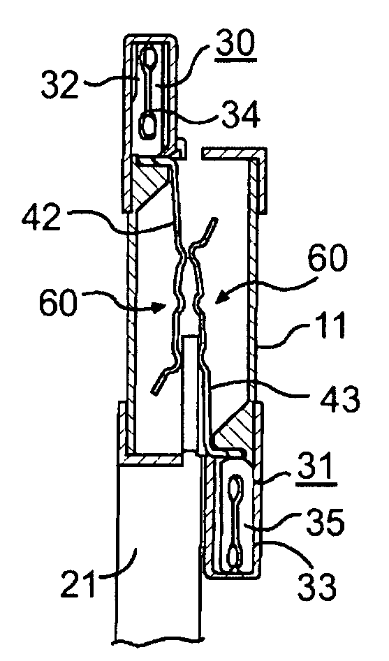
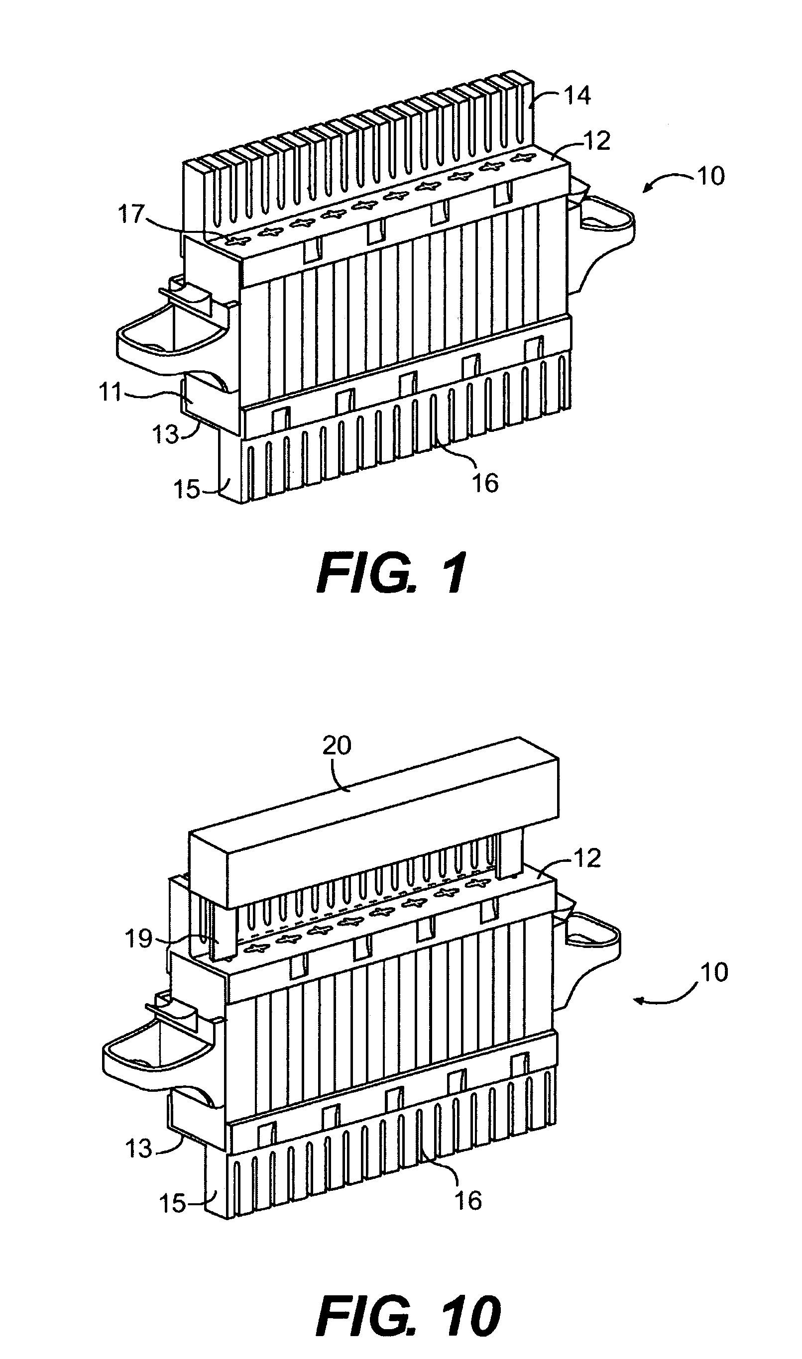
[0025]FIG. 1 illustrates a connector module 10 which can be inserted into a mounting frame (not shown) along with other similar modules 10 to form a connecting block. For details concerning the mounting frame see U.S. Pat. No. 5,595,507, issued to Braun et al., which is incorporated herein by reference.
[0026]The module includes a housing which is made of electrically insulating material, such as plastic. The housing includes an essentially rectangular body portion 11 which is covered by a top cap 14 and a bottom cap 15. The caps 14 and 15 can be made of the same material as the housing and define an upper surface 12 and a lower surface 13 of the housing, respectively.
[0027]Each cap 14 and 15 includes a series of slits 16, which permit insertion of a wire (such as wires 60 and 61 of FIG. 4) therein, as discussed below. Top cap 14 includes a series of slots 17 in the top surface 12. Bottom cap 15 includes a series of slots 18 (see FIG. 4) in the bottom surface 13. The slots 17 and 18 ...
PUM
 Abstract
Description
Claims
Application Information