Plunger needle for an intraocular lens injector

a technology of injector and plunger, which is applied in the field of plunger for intraocular lens injector, can solve the problems of easy torn off, easy to move the lens in an undesired way about the plunger tip and become stuck in the injector, and difficult to insert the lens without damage through anchoring means

Active Publication Date: 2008-02-26
ASICO +1
View PDF10 Cites 33 Cited by
  • Summary
  • Abstract
  • Description
  • Claims
  • Application Information

AI Technical Summary

Benefits of technology

[0010]It is therefore an object of the invention to provide a plunger needle for an intraocular lens injector which permits safe ejection of a folded lens and avoids the latter becoming stuck inside the injector.
[0013]This plunger needle can be produced relatively easily. In the front area, it has a minimal amount of edges, so that the lens is not damaged. In addition, it can be used in different types of injectors and for different lens types. However, the radius of curvature of the front face of the plunger tip is preferably adapted to the respective radius of the lens so that the front face bears optimally on the folded lens and can eject the latter evenly and in a guided manner from the injector. The length of the curvature, here designated by the angle of opening of the cylinder segment, is preferably adapted to the degree of folding of the lens. The curvature is preferably sufficiently long to make contact with a substantial part of the vertical height of the two branches of the folded lens. In addition, the plunger tip is wide enough to ensure that it makes contact with the two branches of the folded lens.
[0014]In a preferred embodiment, the plunger tip has an indentation for receiving a haptic of the lens, so as to prevent damage to the haptic. If, in the area behind the plunger tip, the plunger needle also has a bearing surface flush with the deepest area of this indentation, the safety is still further enhanced.

Problems solved by technology

In addition, measures must be taken to ensure that at no time does the lens move in an undesired way about the plunger tip and become stuck in the injector.
Inserting the lens without damage is made difficult by anchoring means, referred to as haptics, which may be present on the lens.
Since these anchoring means protrude from the folded lens, they can easily become stuck between the plunger and the inner injector wall and be torn off.
The plunger needles known hitherto satisfy these conditions only partially, or can only be used in specially adapted injectors.
This plunger tip is relatively complex and is correspondingly difficult to produce.
In addition, it has a large number of edges, which increases the risk of damaging the lens.

Method used


Image

  • Plunger needle for an intraocular lens injector
  • Plunger needle for an intraocular lens injector
  • Plunger needle for an intraocular lens injector

Examples


Embodiment Construction

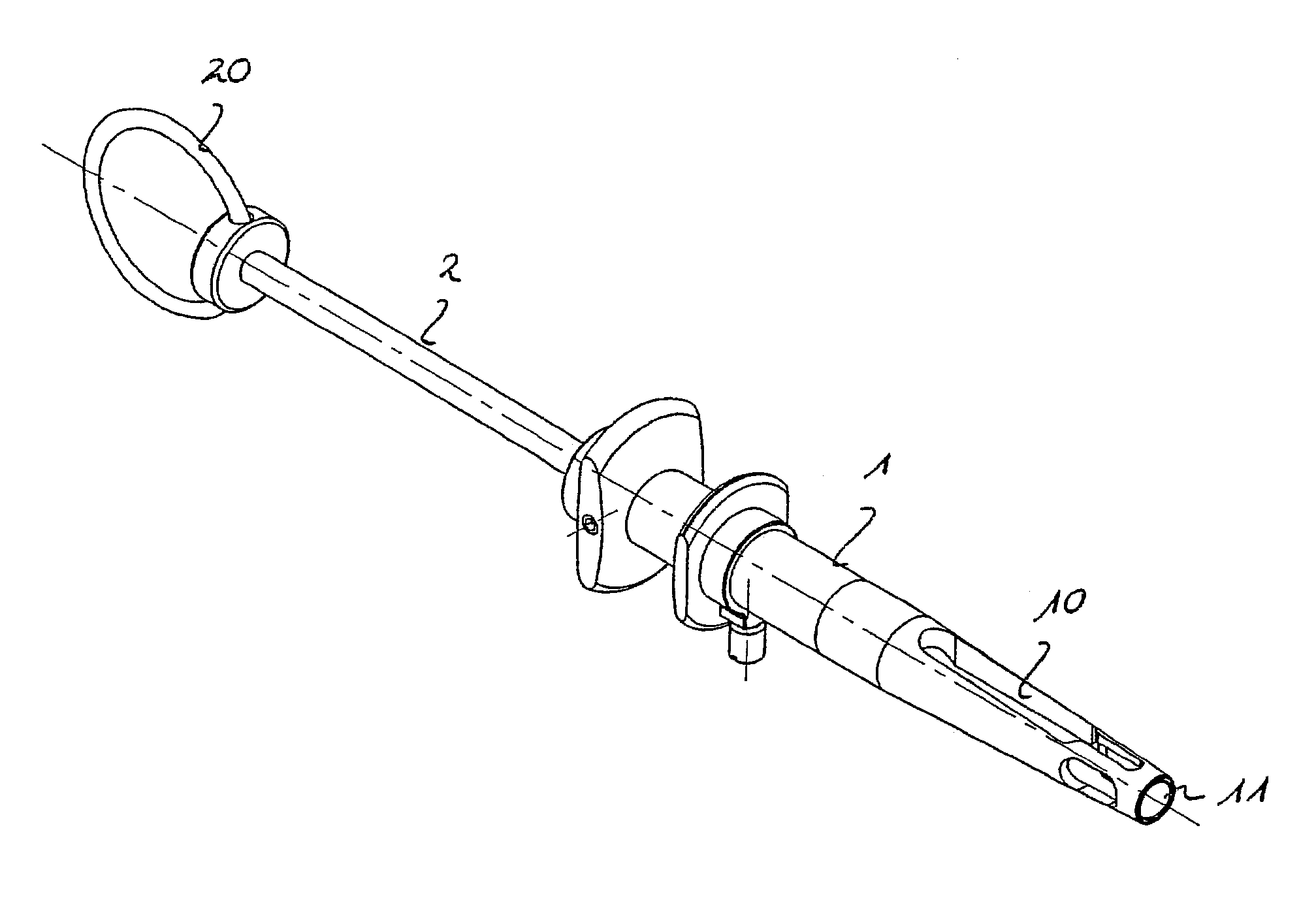
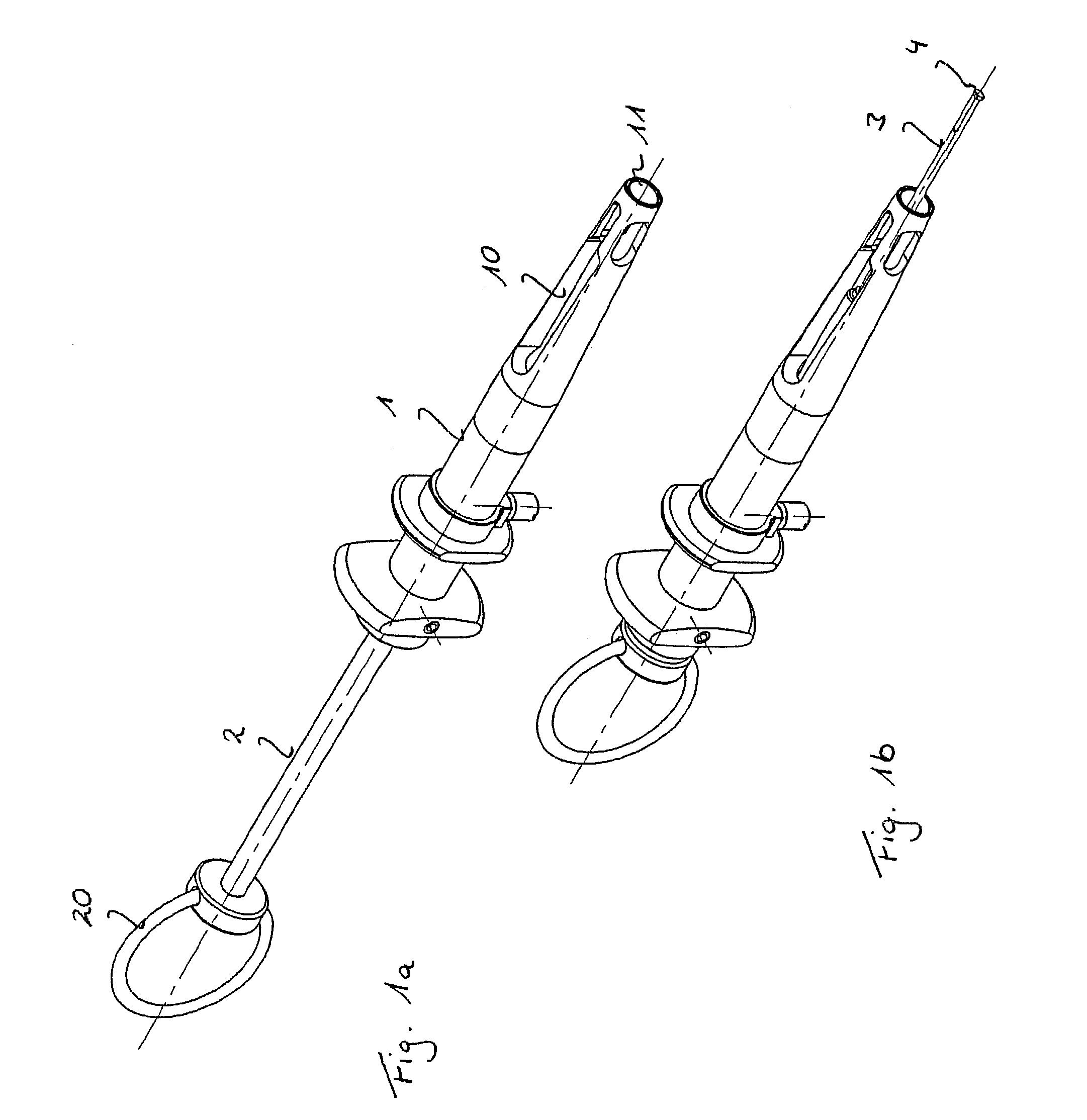
[0046]FIGS. 1a and 1b show an example of an intraocular injector. The embodiments of the plunger needle according to the invention which are described below can, however, also be used in other injectors, particularly the injectors which are standard today.

[0047]The injector has a sleeve-shaped grip body 1 through which a plunger passes. The plunger has a plunger rod 2 with a finger ring 20 arranged at its rear end, in particular for the thumb, and a plunger needle 3 arranged at its front end. The plunger needle 3 can be secured releasably on the plunger rod 2, in particular via a threaded connection.

[0048]The grip body has a lens holder 10 for receiving a lens (not shown here). The lens is usually inserted with a cartridge into the lens holder 10. The cartridge protrudes from the front end of the lens holder. The lens is pushed out of the cartridge by means of the plunger and injected into a patient's eye.

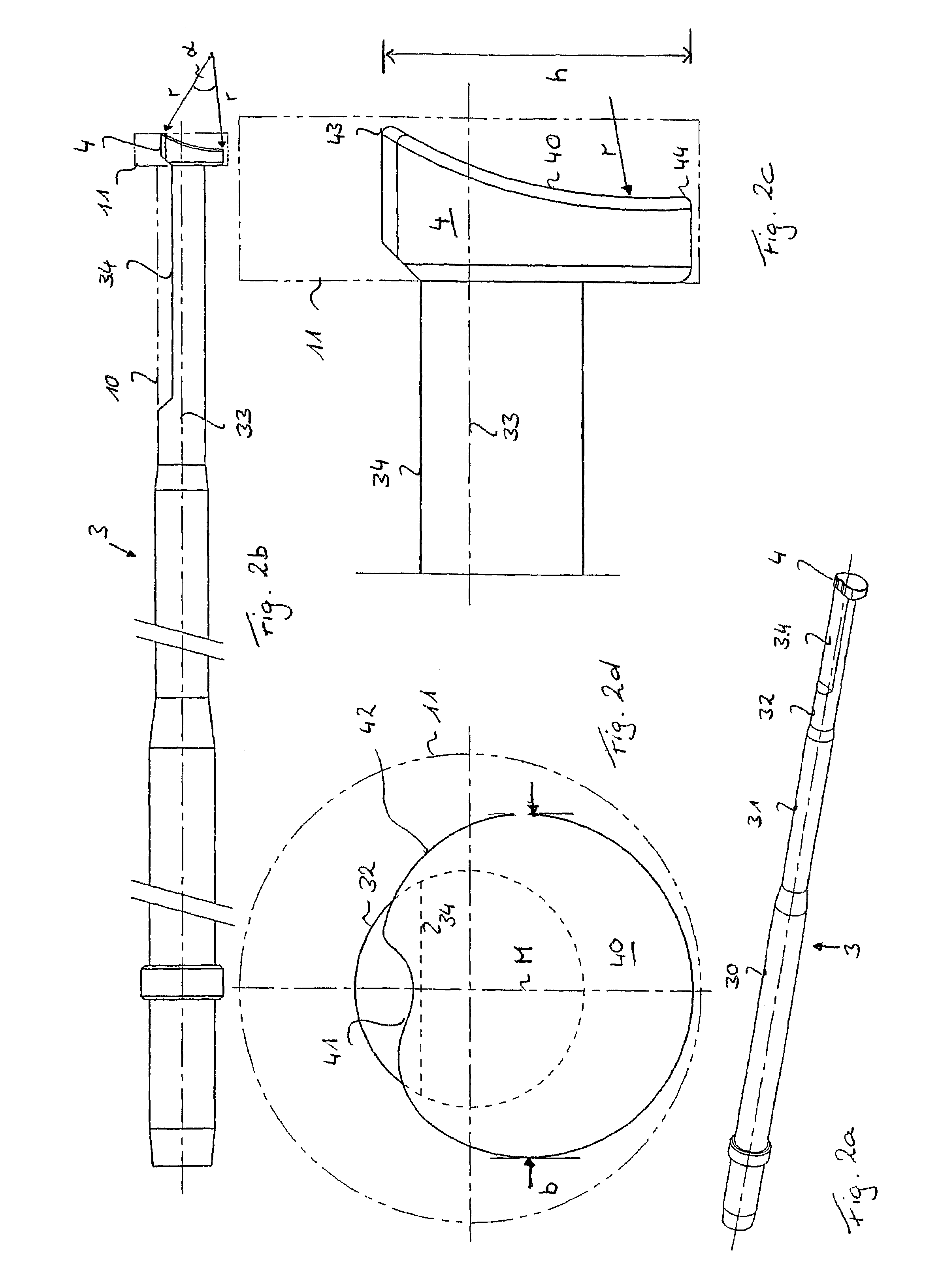
[0049]A first illustrative embodiment of a plunger needle 3 according to the i...


PUM


Abstract

A plunger needle (3) for an intraocular lens injector has a plunger tip (4) with a contact area for making contact with a lens (L), the contact area being arranged in a front face (40) of the plunger tip (4), which is curved cylindrically. The plunger needle (3) according to the invention, with its specially configured plunger tip (3), permits reliable guiding of the lens (L) upon injection into an eye and prevents the lens (L) becoming stuck in the injector. It is also easy to produce.

Description

TECHNICAL FIELD[0001]The invention relates to a plunger needle for an intraocular lens injector.PRIOR ART[0002]Opaque natural lenses can be replaced with artificial lenses called IOLs. In this procedure, the patient's opaque lens is first removed. The artificial lens is then fitted, either manually with the aid of forceps, or using an injector. This injector consists principally of a sleeve-shaped grip body with a lens holder and with a plunger which can be displaced in a guided manner in the grip body. The lens, packed in a cartridge in the folded state, is inserted into the lens holder. In the same way as in a syringe, the lens is injected through an opening into the eye. To do so, the plunger is either pushed forward in a straight line or is turned forward in a guided manner in a thread. The lens is able to unfold in the eye, the unfolding often being assisted by rotation of the plunger.[0003]Various injectors are known in the prior art. A list of the best known types is provided...

Claims


Application Information

Patent Timeline
Patent Type & Authority Patents(United States)
IPC IPC(8): A61F9/00A61F9/007A61F2/16
CPCA61F2/1664
Inventor MEYER, ROLF
Owner ASICO
Why Eureka
Try Eureka