Syringe needle retainer and cap assembly

a technology of syringe and retainer, which is applied in the field of syringes, can solve problems such as the need to use two hands

Inactive Publication Date: 2019-11-07
KARIMI KAVEH
View PDF0 Cites 0 Cited by
  • Summary
  • Abstract
  • Description
  • Claims
  • Application Information

AI Technical Summary

Benefits of technology

[0018]When injections are complete (whether an operator exchanged ampoules or not), the outer cap may be moved to cover the needle again. In doing so, the guide pin is moved through the release channels of the syringe body and the needle retainer and into the locking channel of the needle retainer. The needle retainer may also have permanent locking means to secure the guide pin permanently once the operator is ready to dispose of a needle. For example, a locking channel of the needle retainer may include a retaining catch that allows the guide pin to move past the retaining catch, but once the guide pin does move past the retaining catch it cannot move past the retaining catch again. In this way, the outer cap may be locked in position to the needle retainer such that the needle is covered and the needle assembly may be ejected from the syringe body safely. In addition, as the needle assembly is ejected from the syringe body, the outer cap is also ejected and stays securely covering the needle because the outer cap is permanently affixed to the needle retainer.

Problems solved by technology

The result is the necessity of the operator to use both hands in order to free the ampoule, which is undesirable with respect to efficiency and hygienic safety.
An additional drawback of prior art syringe 15 is the need to use two hands in the removal of the used needle assembly which is also to be discarded, for the same reasons of hygienic safety and efficiency.

Method used


Image

  • Syringe needle retainer and cap assembly
  • Syringe needle retainer and cap assembly
  • Syringe needle retainer and cap assembly

Examples


Embodiment Construction

[0028]While this invention is susceptible of embodiment in many different forms, there is shown in the drawings and will be shown in detail herein, several specific embodiments, with the understanding that the present disclosure is to be considered as an exemplification of the principles of the invention and is not intended to limit the invention to the embodiments illustrated.

The Prior Art

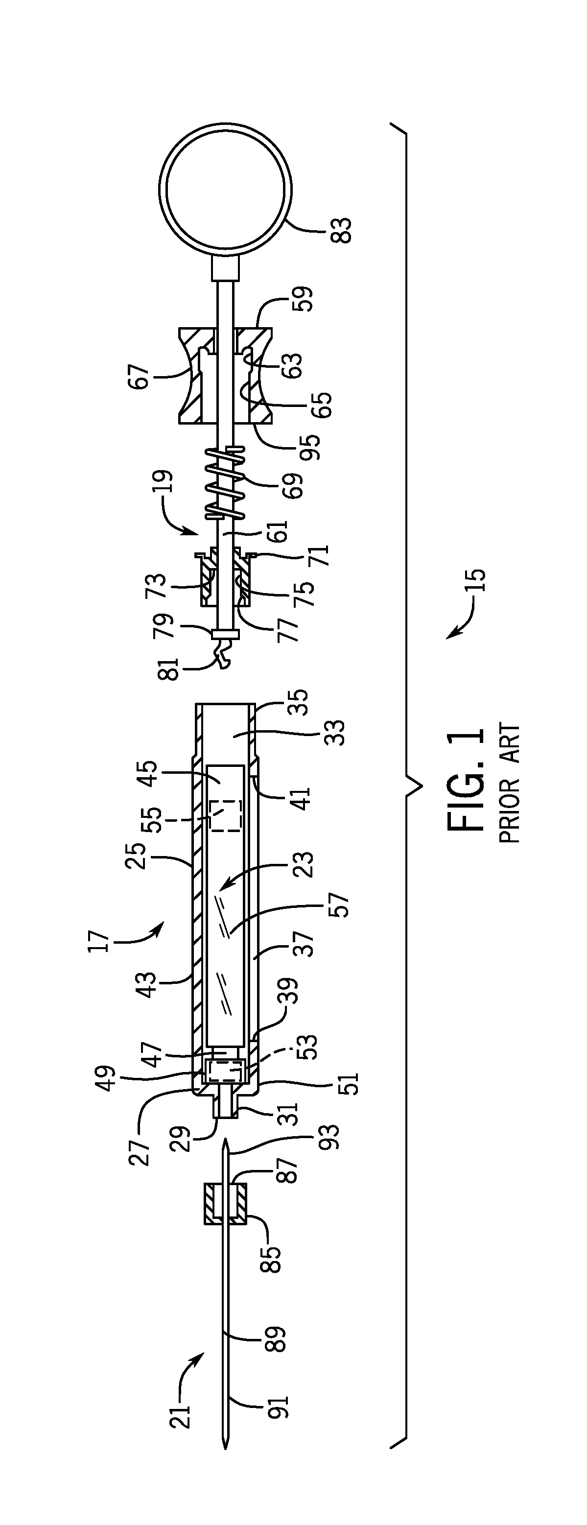
[0029]A prior art syringe 15 is shown in partially exploded sectional view in FIG. 1. Syringe 15 is composed of syringe body 17, plunger assembly 19, needle assembly 21, and interchangeable, disposable ampoule 23.

[0030]Syringe body 15 is formed as a substantially hollow cylinder 25, having a substantially closed forward end 27 with coupling 29 having thread 31, and a substantially open rear end 33 with thread 35. In addition, a lateral aperture 37, bounded by front edge 39 and rear edge 41, is provided. Lateral aperture 37 has a width (not illustrated) which is sufficient to accommodate the width ...


PUM


Abstract

A syringe cap and needle assembly includes a needle retainer, a needle member secured within the needle retainer, and a cap. The needle member further includes an exterior needle end that extends outside of a forward end of the needle retainer. The cap is configured to slideably move with respect to the needle retainer between at least a first position and a second position. in the first position, the cap substantially surrounds the exterior needle end. In the first position and the second position, the cap substantially surrounds at least a portion of the needle retainer. in the second position, at least a portion of the exterior needle end is not surrounded by the cap.

Description

CROSS REFERENCE TO RELATED APPLICATION[0001]This application claims priority to and the benefit of U.S. Provisional Appln. No. 62 / 665,245, filed on May 1, 2018, the disclosure of which is incorporated herein by reference in its entirety.BACKGROUND[0002]The present invention is directed generally to syringes for hypodermic needles, and in particular an improved syringe body, syringe needle assembly, and cap assembly that covers a syringe needle assembly with a cap before, during, and / or after use to prevent injury from the needle and possible exposure of the needle to contamination or disease before, during, and / or after use.[0003]The present improved syringe body, syringe needle assembly, and cap assembly is disclosed herein in the context of syringes which are configured to enable the use of prepared ampoules, which ampoules contain a measured amount of medicinal or other liquid, and which are inserted into the syringe, and removed and discarded after use, and in particular to an i...

Claims


Application Information

Patent Timeline
Patent Type & Authority Applications(United States)
IPC IPC(8): A61M5/32A61M5/24
CPCA61M5/3269A61M5/2459A61M2005/2407A61M2005/2481A61M5/3204A61M5/2466A61M2005/247A61M5/24A61M5/3202A61M5/3257A61M5/3272A61M5/3205A61M2005/3206A61M2005/3247
Inventor KARIMI, KAVEH
Owner KARIMI KAVEH
Why Eureka
Try Eureka