Valve assembly and method

a valve and assembly technology, applied in the direction of valve details, valve arrangements, spindle sealings, etc., can solve the problems of cumbersome and time-consuming conventional methods of removing the valve packing, and the fluid may leak through the bore, so as to achieve the effect of less compression force and effective removal of the packing

Active Publication Date: 2016-10-25
MARSHALL EXCELSIOR CO
View PDF22 Cites 9 Cited by
  • Summary
  • Abstract
  • Description
  • Claims
  • Application Information

AI Technical Summary

Benefits of technology

[0009]Accordingly, the valve assembly and method provide effective removal of the packing from the bore of the valve assembly. The second biasing member is configured to eject the packing from the bore to remove all of the packing easily from within the bore. As such, removal of the packing is not cumbersome or time consuming. Additionally, the valve member advantageously employs the second biasing member for safely ejecting the packing beyond the retainer end of the housing. Furthermore, the second biasing member allows the packing to be replaced back within the bore using less compression force when reattaching the retainer to the housing.

Problems solved by technology

As the valve packing ages or wears, fluid may leak through the bore.
Conventional methods of removing the valve packing are cumbersome and time consuming.

Method used


Image

  • Valve assembly and method
  • Valve assembly and method
  • Valve assembly and method

Examples


Embodiment Construction

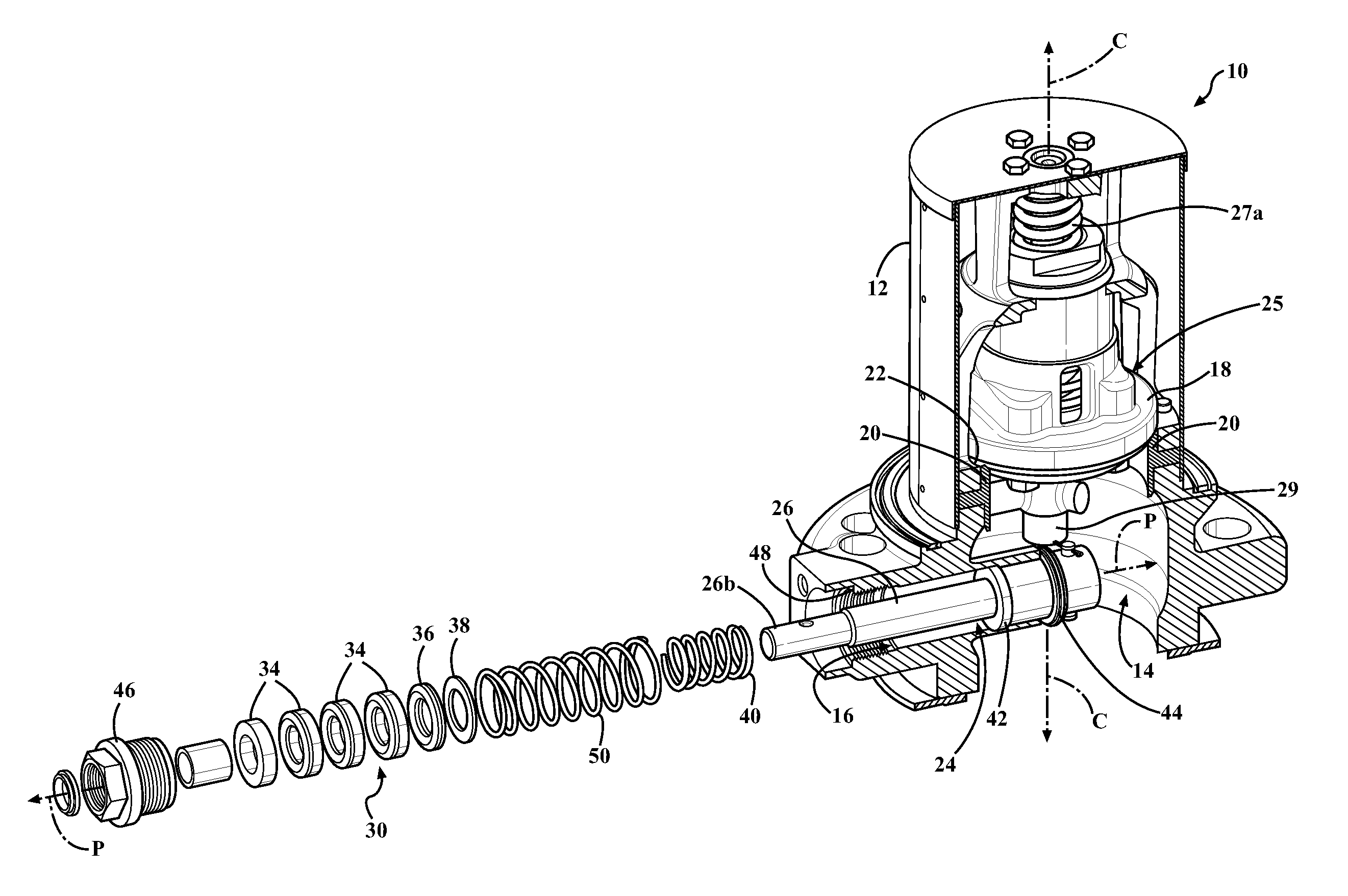
[0017]Referring to the Figures, wherein like numerals indicate like or corresponding parts throughout the several views, a valve assembly is generally shown at 10. The valve assembly 10 is utilized to manipulate fluid transfer. The fluid can be liquid petroleum gas (LP-Gas), anhydrous ammonia (NH3) or any other suitable fluid.

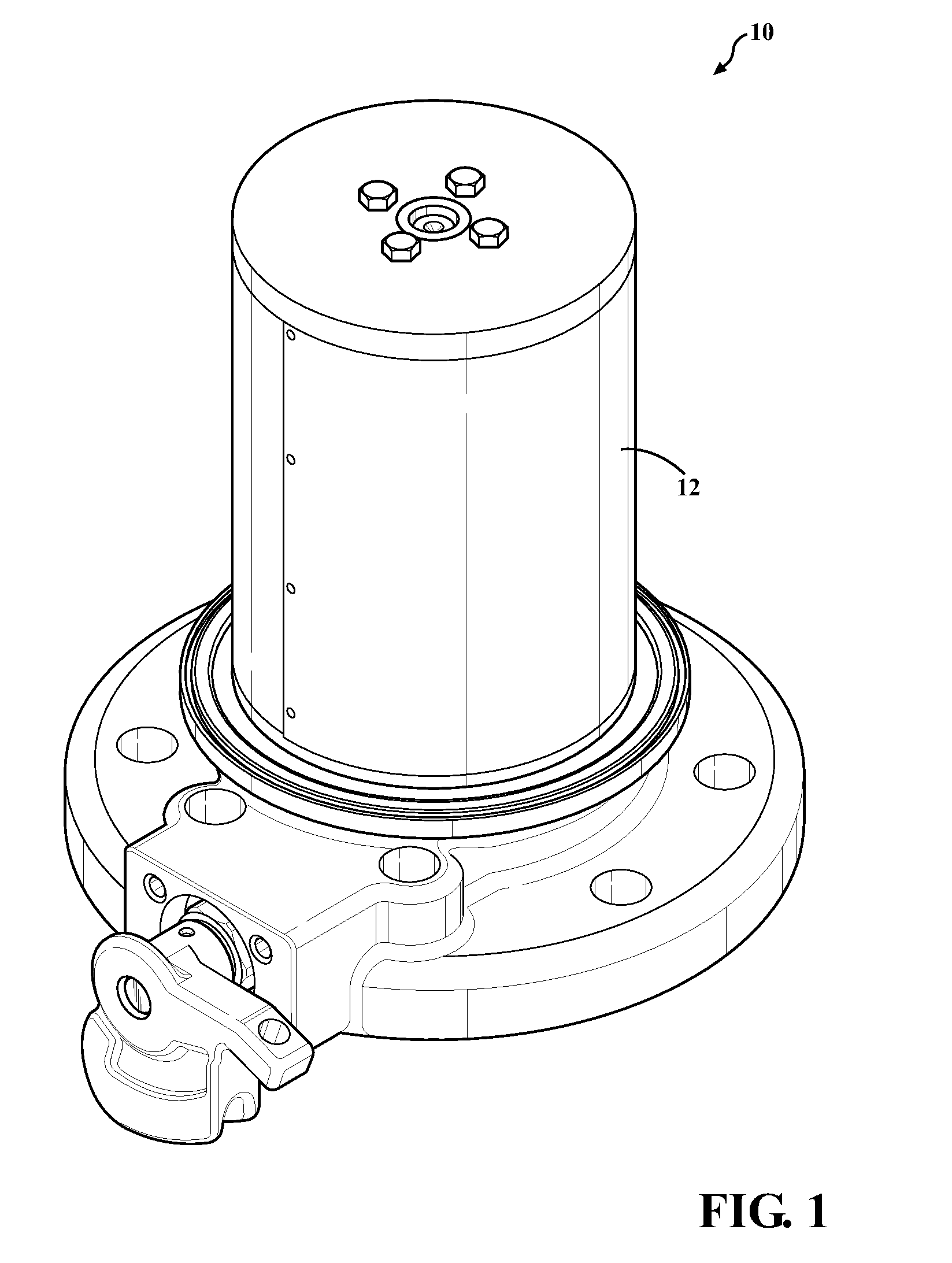
[0018]The valve assembly 10 is typically mounted to a tank (not shown) storing the fluid. The valve assembly 10 may be mounted to an inlet or outlet of the tank for filling or withdrawing fluid from the tank. The valve assembly 10 may also be mounted to inlets or outlets of transport truck tanks. Any suitable method may be utilized to secure the valve assembly 10 to the tank.

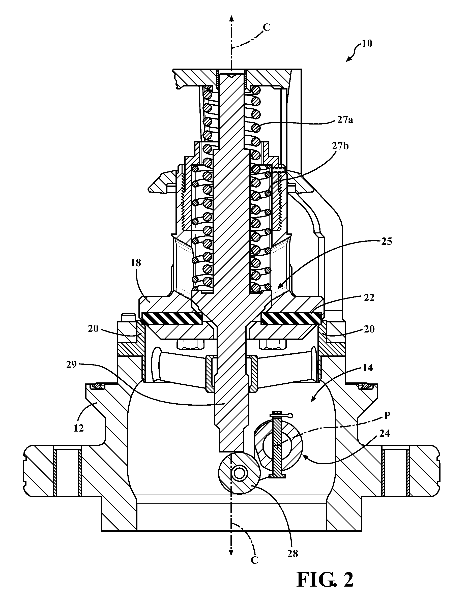
[0019]Referring to FIGS. 1 and 2, the valve assembly 10 includes a housing 12. The housing 12 defines a cavity 14. The cavity 14 extends along a central axis C. As shown in FIG. 3, the housing 12 further defines a bore 16 which opens into the cavity 14. The cavity 14 and the bore 16 are adj...


PUM


Abstract

A valve assembly includes a housing defining a cavity and a bore which opens into the cavity. A valve member is disposed in the cavity. The valve member moves between an open position for allowing fluid flow through the housing and a closed position for preventing fluid flow through the housing. An actuator extends through the bore for moving the valve member between the open and closed positions. A packing is positionable in the bore to provide a seal about the actuator for preventing fluid from exiting the housing through the bore. The packing is ejectable from the bore. The valve assembly includes a first and second biasing member. The first biasing member is configured to apply a first force to the packing to provide the seal. The second biasing member is configured to apply a second force to the packing for ejecting the packing from the bore.

Description

CROSS-REFERENCE TO RELATED APPLICATIONS[0001]The subject patent application claims priority to and all the benefits of U.S. Provisional Patent Application No. 61 / 587,821 which was filed on Jan. 18, 2012, which is hereby expressly incorporated herein by reference.BACKGROUND OF THE INVENTION[0002]1. Field of the Invention[0003]The present invention relates to a valve assembly for transferring fluid.[0004]2. Description of the Related Art[0005]Valve assemblies, such as those for transferring fluid, are known in the art. One type of valve assembly includes a housing defining a cavity. A valve member is movable within the housing for controlling fluid transfer. The housing defines a bore which opens into the cavity. An actuation device is typically disposed through the bore for moving the valve member between an open position for enabling fluid transfer and closed position for preventing fluid transfer through the housing. Such valve assemblies generally include a valve packing which is ...

Claims


Application Information

Patent Timeline
Patent Type & Authority Patents(United States)
IPC IPC(8): F16K31/524F16K41/00
CPCF16K31/524F16K41/00Y10T137/0491
Inventor BLANCHARD, FREDERICK W.COY, NATHAN H.
Owner MARSHALL EXCELSIOR CO
Why Eureka
Try Eureka