
Adjustable rail apparatus for external fixation systems

a fixation system and adjustable technology, applied in the direction of external osteosynthesis, osteosynthesis devices, etc., can solve the problems of cumbersome and/or time-consuming, limited relative positioning and orientation between two or more clamps coupled to the rail, and the removal of parts of the clamp assembly

Pending Publication Date: 2021-06-24
AMDT HLDG INC
View PDF0 Cites 1 Cited by
  • Summary
  • Abstract
  • Description
  • Claims
  • Application Information

AI Technical Summary

Benefits of technology

The present disclosure provides external fixation systems that allow for adjustable and selective fixation of bones and tissues. The systems include an adjustable rail apparatus with clamps that can be locked in place along the rail, allowing for flexibility in positioning and orientation. The clamps can be rotated and translated along the rail, providing greater stability and secure fixation. The joint apparatus allows for the selective adjustment of the relative angular and rotational arrangement of the external fixation beam elements. The technical effects of the invention include improved stability and flexibility in external fixation, allowing for greater precision and ease of use in medical procedures.

Problems solved by technology

However, the beam element itself is typically linear and static (i.e., is not adjustable out of the linear shape or pathway).
The relative positioning and orientation between two or more clamps coupled to the rail is thereby limited by the linear nature of the rail.
Further, adding or removing parts of the clamp assemblies and / or additional segments or extensions to the rail to suit a particular anatomical or fixation arrangement can be cumbersome and / or time consuming.

Method used


Image

  • Adjustable rail apparatus for external fixation systems
  • Adjustable rail apparatus for external fixation systems
  • Adjustable rail apparatus for external fixation systems

Examples


Embodiment Construction

[0049]When introducing elements of various embodiments of the present disclosure, the articles “a,”“an,”“the,” and “said” are intended to mean that there are one or more of the elements. The terms “comprising,”“including,” and “having” are intended to be inclusive and mean that there may be additional elements other than the listed elements. Any examples of parameters are not exclusive of other parameters of the disclosed embodiments. Components, aspects, features, configurations, arrangements, uses and the like described, illustrated or otherwise disclosed herein with respect to any particular embodiment may similarly be applied to any other embodiment disclosed herein.

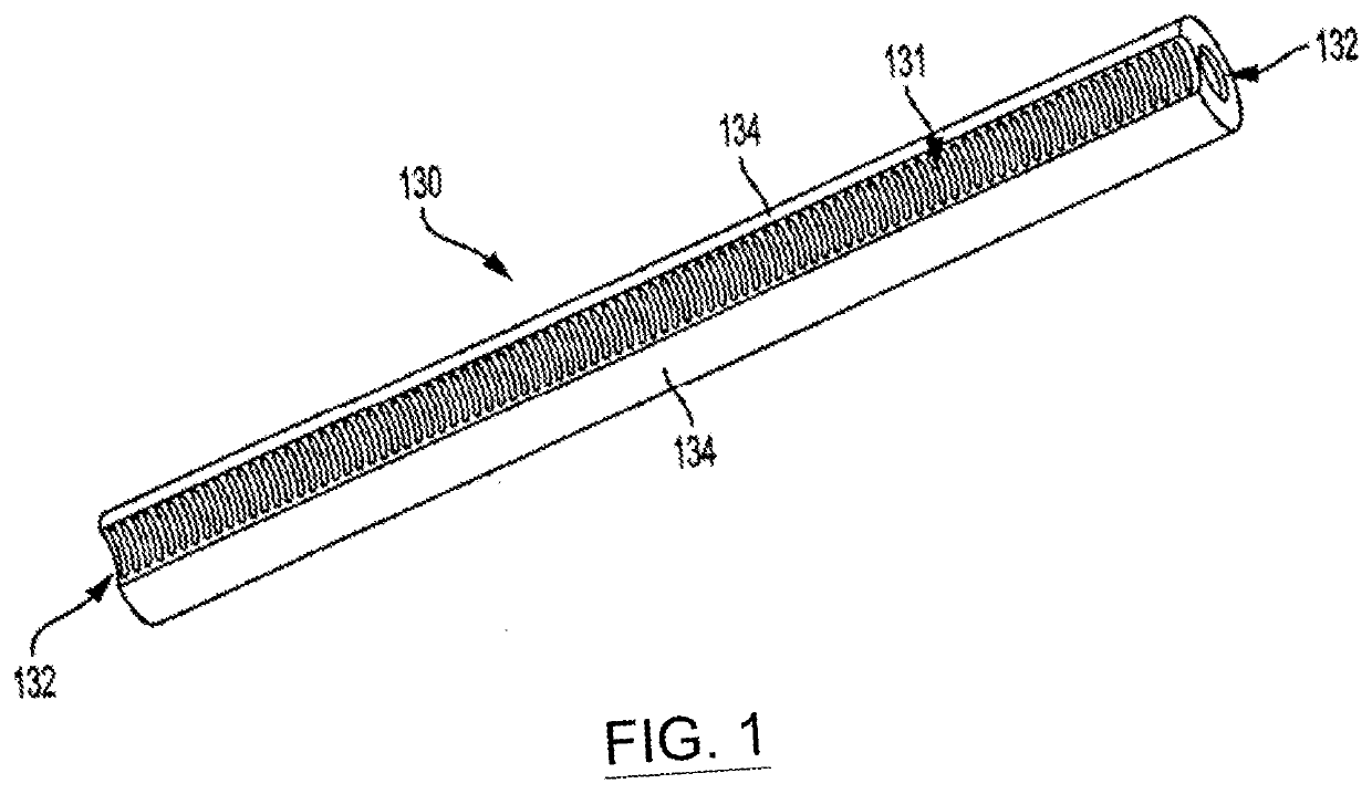
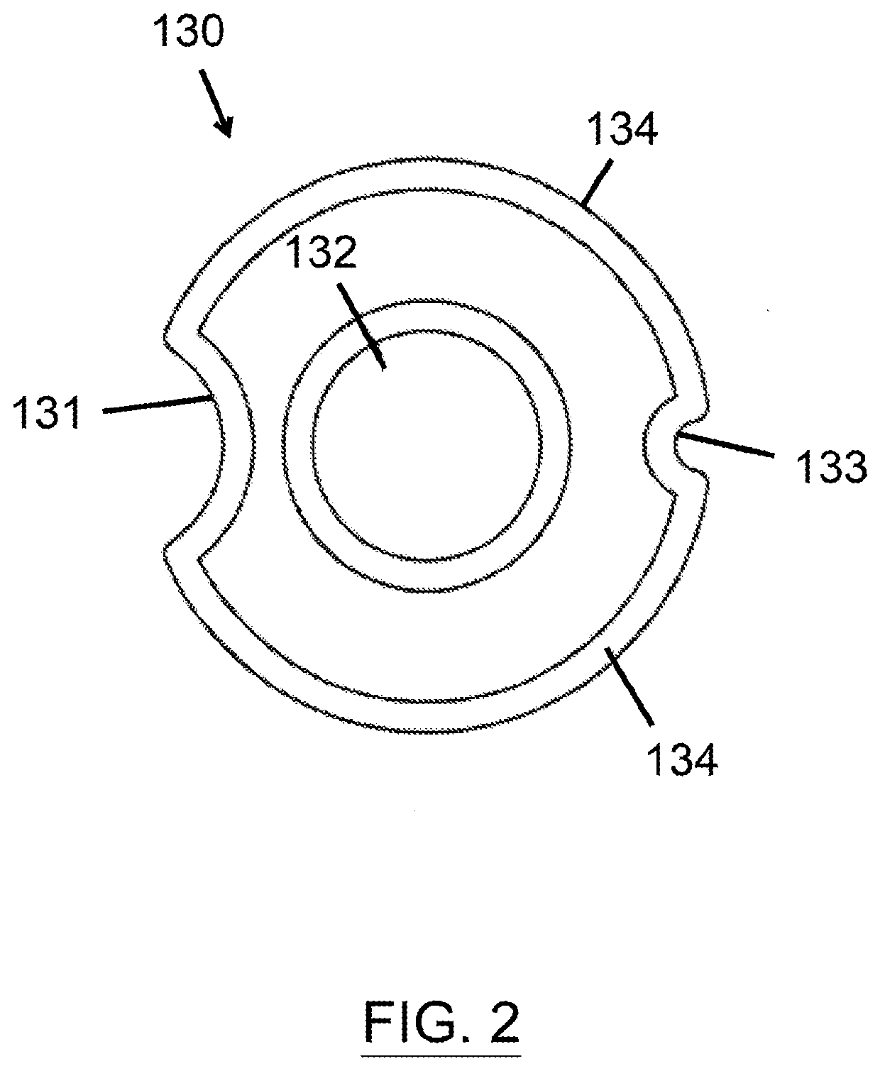
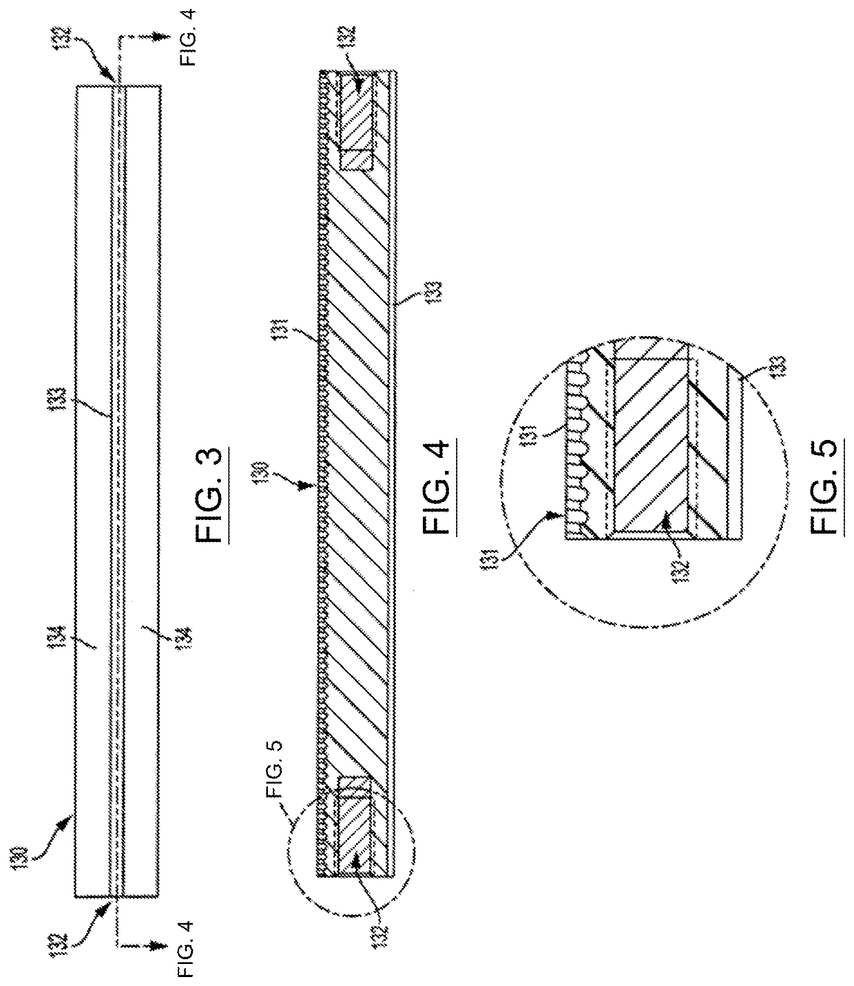
[0050]The present disclosure provides for external bone or tissue fixation systems and related fixation methods 100, as shown in FIGS. 6-26. The fixation systems and methods 100 include one or more independently drivable clamp assembly (not shown) (which may provide at least 3DOF) that are each translatable or drivab...


PUM


Abstract

Adjustable rail apparatuses and external bone and / or tissue fixation system including an adjustable rail apparatus is disclosed. The rail apparatuses comprise first and second external fixation beam elements with alignment grooves, and a joint coupling the first and second beam elements and configured to selectively adjust the relative angular and rotational arrangement of the first and second beam elements. The joint also comprises a first and second beam end housings rotationally fixed to the first and second external fixation beam elements, respectively. The joint also comprises first and second clamp members axially and rotationally fixed to the first and beam end housings, respectively. The joint also comprises first and second rotation end housings coupled with the first and second clamp members, respectively, the first and second rotation end housings being selectively rotatably adjusted with respect to the first and second clamp members, respectively, within fixed ranges of rotation.

Description

CROSS-REFERENCE TO RELATED APPLICATIONS[0001]This application claims priority benefit from International Application No. PCT / US2019 / 049828 filed on Sep. 5, 2019, which claimed priority from U.S. Provisional Application No. 62 / 727,116 filed Sep. 5, 2018, each of which is incorporated herein by reference in its entirety.FIELD OF THE INVENTION[0002]The present disclosure is generally directed to rails for external bone fixation systems and related methods. More particularly, the present disclosure is directed to adjustable rails for external bone fixation systems and related methods that allow adjustability between the orientation between two or more rail portions.BACKGROUND OF THE INVENTION[0003]External fixation devices have been used to treat bone and tissue conditions by positioning bone or tissue segments in desired relative positions based on particular clinical needs. One form of external fixation devices is a unilateral or mono-lateral rail based fixation device. These devices ...

Claims


Application Information

Patent Timeline
Patent Type & Authority Applications(United States)
IPC IPC(8): A61B17/64A61B17/66
CPCA61B17/6458A61B17/66A61B17/6475A61B17/6483A61B17/6425
Inventor MULLANEY, MICHAEL W.
Owner AMDT HLDG INC
Learn More