
Injection and compression molding with parallelism mechanism

Active Publication Date: 2006-05-09
TEIJIN CHEM LTD
View PDF13 Cites 6 Cited by
  • Summary
  • Abstract
  • Description
  • Claims
  • Application Information

AI Technical Summary

Benefits of technology

[0130]According to the injection compression-molding method, the volume ratio of the cavity 12 in an intermediate clamped state relative to the volume of a target molded article is 1.2 or more, preferably, 1.3 or more, furthermore preferably 1.4 or more, and most preferably 1.5 or more. The effect of the invention increases as the ratio increases. However, exceedingly high ratio may lower the molding efficiency and cause defect in molded articles such as jetting. In view of this, it is preferable to set the upper limit of the ratio at 3 or less, and more preferably at 2 or less.
[0131]In the injection compression-molding method, it is preferable to set a state where the parting surfaces of the molds 10 and 11 do not contact with each other as a final clamped state.
[0132]It is possible to perform molding in a contact state of the molds 10 and 11 according to the injection compression-molding method. However, the non-contact state where the parting surfaces of the molds 10 and 11 do not contact with each other is advantageous as a final clamped state because it provides more uniform compression of melted resin in the cavity 12 and provides injection compression-molded articles of less strain with less compression force (clamping force).
[0133]In case where the parting surfaces of the molds 10 and 11 contact with each other, it is likely that a specified pressure may not be exerted to the melted resin in the cavity 12, with the result that molded articles may suffer from surface sink or the like, leading to failure in attaining a specified precision in dimensions.
[0134]According to the injection compression-molding method, high parallelism is secured between the molds 10 and 11 as described above.
[0135]Accordingly, even if the parting surfaces of the molds 10 and 11 do not contact with each other, a desired molded article is producible without causing variation in thickness. Thus, the injection compression-molding method provides molded articles of high-quality by rendering the parting surfaces of the movable mold and the fixed mold substantially in non-contact state with each other in a final clamped state.

Problems solved by technology

In the above conventional injection molding method, it is highly likely that a large residual stress remains in a molded article.
With such a large residual stress remaining in a molded article, it is highly likely that strain or refractive index in the molded article exceeds a permissible range if such a molded article is to be used for special purposes such as parts for precision instruments and optical instruments.
Consequently, in the case where molded articles are produced by the above injection compression-molding method, there rises a problem, as shown in FIG. 9, that parallelism of parting surfaces of molds 91, 92 is not maintained due to, for example, flexure of a guide member 93, with the result that quality of molded articles may be deteriorated.

Method used


Image

  • Injection and compression molding with parallelism mechanism
  • Injection and compression molding with parallelism mechanism
  • Injection and compression molding with parallelism mechanism

Examples


example 1

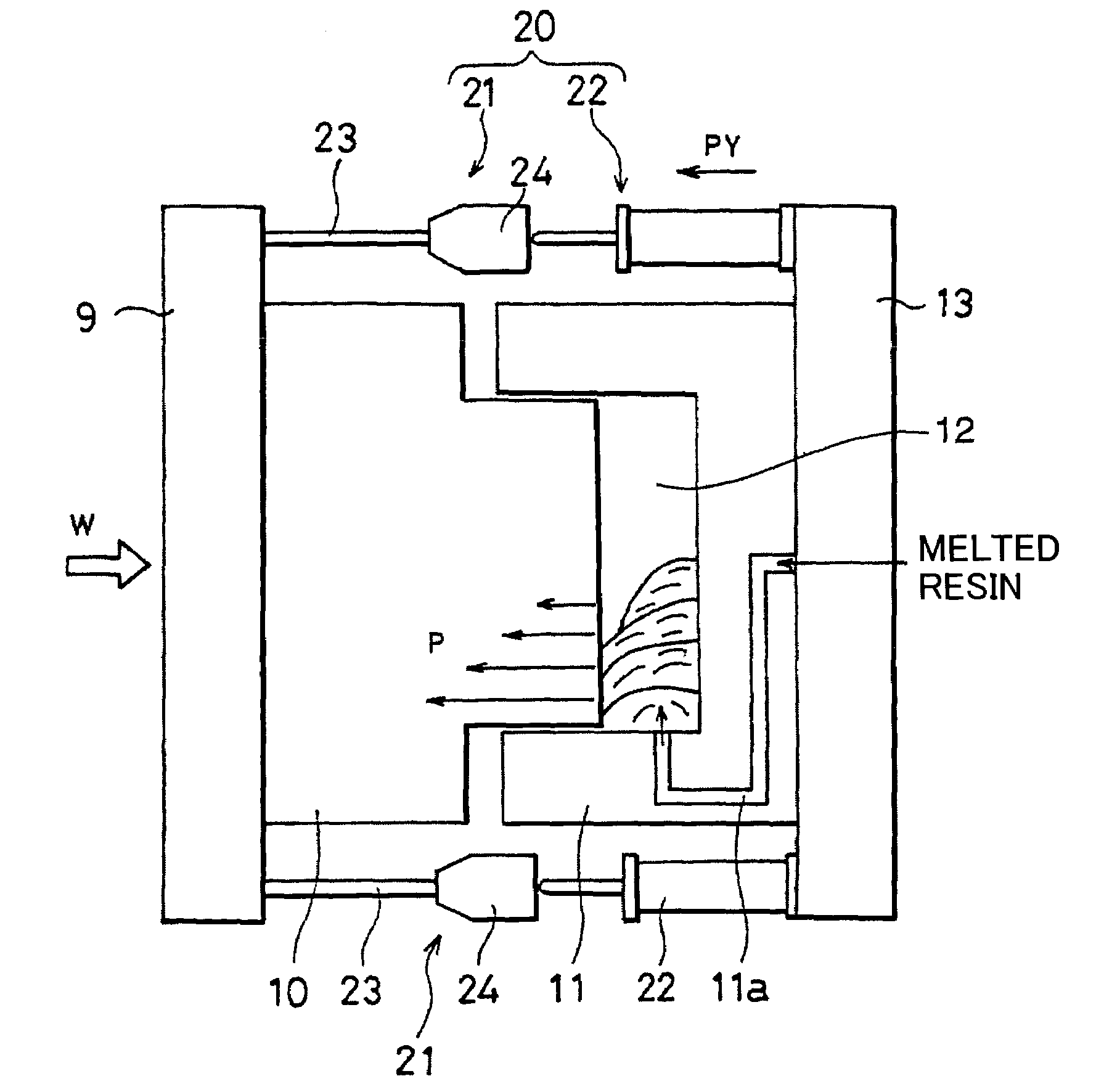
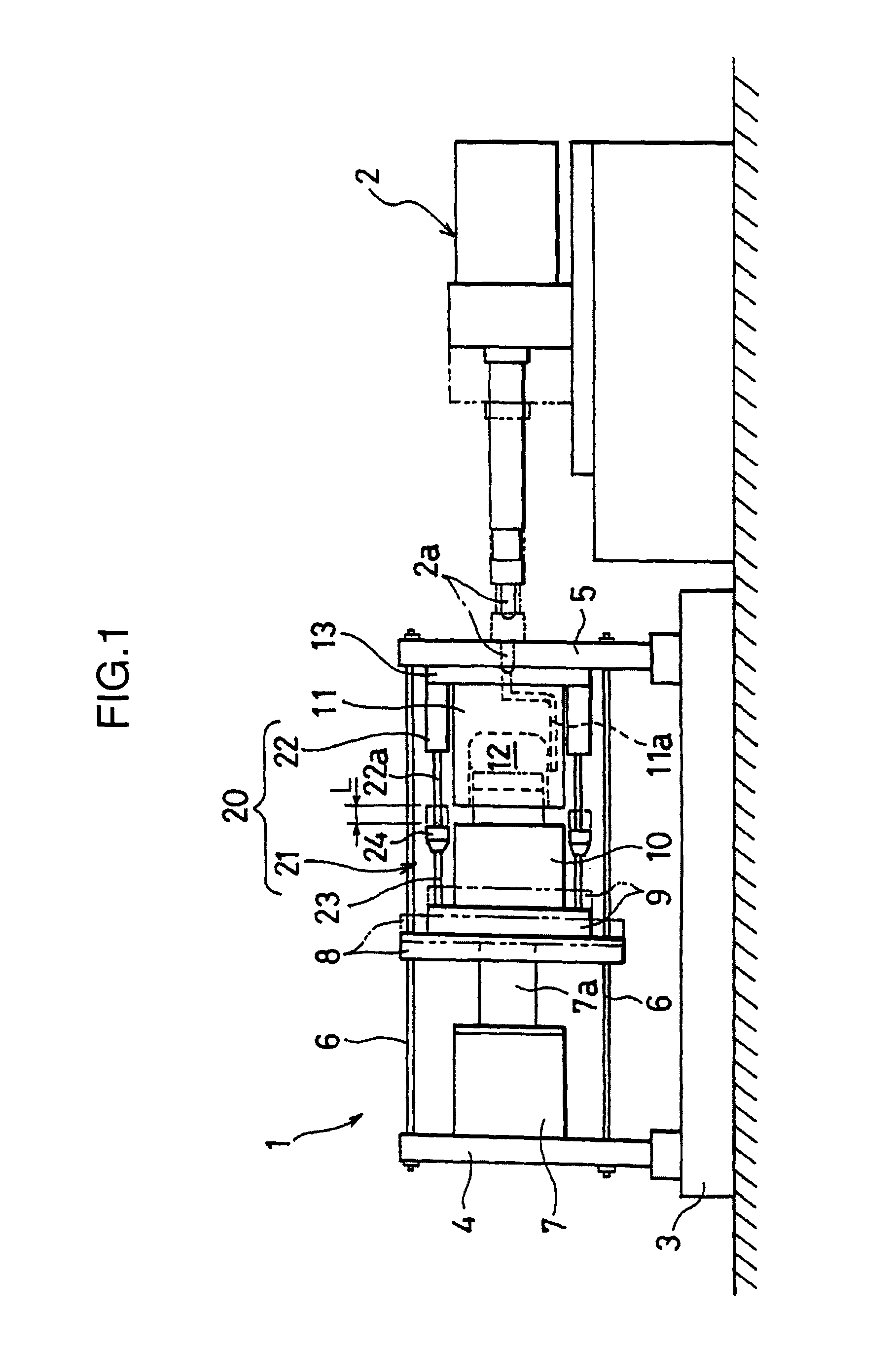
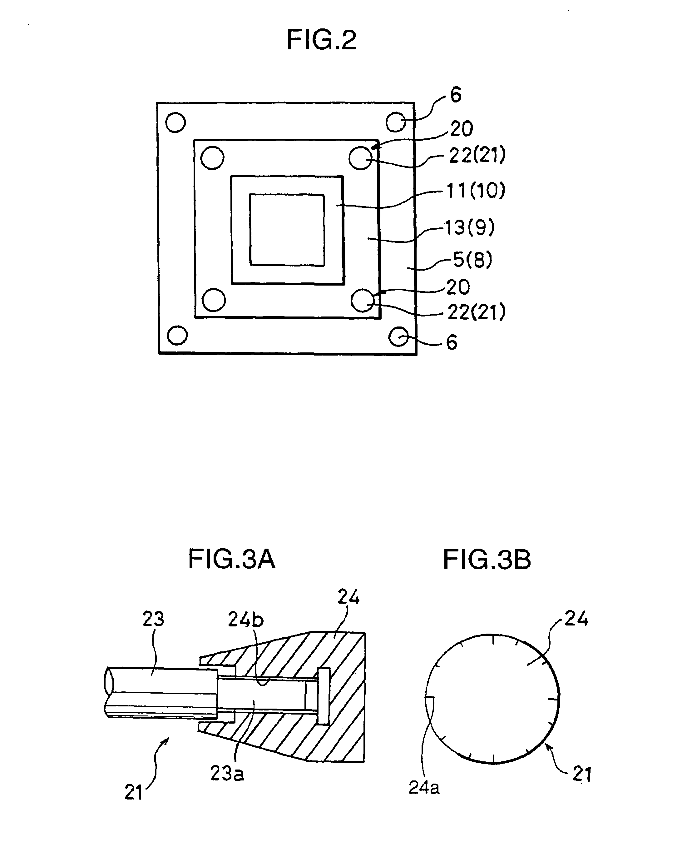
[0182]The polycarbonate resin pellets PC-1 were dried at 120° C. for 5 hours by a hot air dryer, and injection molding was performed by an injection molding apparatus J1300E-C5 produced by Japan Steel Works, Ltd. with cylinder diameter: 110 mm and clamping force: 12,700 kN (produced according to the specifications in which the hydraulic circuit and the control system were so modified as to enable compression molding). The parallelism retaining mechanism 20 was mounted at four corners of the mold attaching plates as shown in FIG. 1. Micrometers were attached as the head members 24. Parallelism as preparatory operation was implemented to secure parallelism between the molds when the molds were set to a specified intermediate clamped state. Then, injection compression-molding was carried out to produce a molded article having the dimensions of about one-half of a glazing member for automotive vehicle as shown in FIG. 7 (projection area of article: about 2,100 cm2, thickness of article:...

example 2

[0189]The polycarbonate alloy resin pellets PC-2 were dried at 120° C. for 5 hours by a hot air dryer, and a molded article having dimensions (projection area of article: about 2,100 cm2, thickness of article: about 3 mm) having dimensions of about one-half of a rear door for automotive vehicle as shown in FIGS. 8A through 8C was produced by using the same apparatus as in Example 1 (in a state that the parallelism retaining mechanisms were activated).

[0190]FIGS. 8A through 8C are diagrams showing the molded article produced in Example 2. FIG. 8A is a front view of the molded article. FIG. 8A shows the front view of the molded article that is projected against the platen plane at the time of molding. Accordingly, the projection area corresponds to the maximal projection area of the molded article.

[0191]It should be appreciated that a gate is located at a lower part of the molded article. FIG. 8B is a sectional view taken along the line C—C in FIG. 8A, wherein the line C—C is aligned ...

example 3

[0205]The polycarbonate resin pellets PC-1 were dried at 120° C. for 5 hours by a hot air dryer, and a Fresnel lens having a convex part of about 25 μm in height (projection area of article: about 1,100 cm2, thickness of article: about 0.7 mm) was produced by using the same apparatus as in Example 1 (in a state that the parallelism retaining mechanisms were activated).

[0206]Cylinder temperature: 310° C., and hot runner temperature: 320° C. were set as the molding conditions. Further, the following high-speed heating-and-cooling molding was carried out while setting the base temperature of the mold at 100° C.

[0207]According to the high-speed heating-and-cooling molding, resin filling was terminated under the rapid heating conditions where the highest temperature of the cavity of the molds reaches 200° C. with use of a heater which follows a cooling process where the molds were rapidly cooled by passing a refrigerant of about 10° C. with use of a chiller unit. The resin filling time w...


PUM

PropertyMeasurementUnit
Percent by massaaaaaaaaaa
Fractionaaaaaaaaaa
Fractionaaaaaaaaaa

Abstract

In an injection compression-molding apparatus, a molded article is produced by setting molds 10 and 11 to an intermediate clamped state, and then by setting the molds 10 and 11 to a final clamped state by re-clamping the molds 10 and 11 to each other after injecting melted resin into a cavity defined by the molds 10 and 11. The apparatus includes a clamping mechanism and a parallelism retaining mechanism 20. The clamping mechanism has a mold-driving cylinder 7 for moving the movable mold 10 toward and away from the fixed mold 11, a guide engaging member 8, support panels 4, 5, etc. so as to selectively set the molds 10 and 11 to the intermediate clamped state and the final clamped state. The parallelism retaining mechanism 20 retains parallelism between the molds 10 and 11 in the intermediate clamped state by giving a corrective force to mold attaching surfaces of the clamping mechanism where the respective molds 10 and 11 are mounted.

Description

TECHNICAL FIELD[0001]This invention relates to an injection compression-molding apparatus for producing molded articles by setting molds to an intermediate clamped state and a final clamped state, an injection molding-compression method, injection compression-molded articles producible by such a method, and thermoplastic resinous articles.BACKGROUND ART[0002]Conventionally, injection molding apparatus comprises a clamping base, a pair of upstanding support panels provided at opposite ends of the clamping base, a guide member which extends horizontally between the support panels, a movable mold which is slidably movable along the extending direction of the guide member, a fixed mold which is fixedly mounted on one of the support panels as opposed to the movable mold, and a mold-driving cylinder which is fixedly mounted on the other one of the support panels to slidingly move the movable mold toward and away from the fixed mold.[0003]Generally, in performing injection molding with the...

Claims


Application Information

Patent Timeline
IPC IPC(8): B29C45/56B29C45/26B29C45/67B29C45/70B29C45/80
CPCB29C45/561B29C2045/1788B29C45/67
Inventor NAGAOKA, TSUTOMUHOTAKA, TOSHIAKI
Owner TEIJIN CHEM LTD
Learn More