
Hybrid seal and planar arrangement comprising at least one high temperature electrochemical cell and a hybrid seal

a high temperature electrochemical cell and hybrid seal technology, which is applied in the direction of fuel cell details, electrolysis components, electrochemical generators, etc., can solve the problems of air or gas in the flow field for oxidizing gas contamination by chemicals, shear or tensile stress, etc., and achieve low shear and tensile strength, simplify the job, and reduce the effect of oxidizing gas contamination

Inactive Publication Date: 2019-12-12
SOLIDPOWER SA
View PDF0 Cites 3 Cited by
  • Summary
  • Abstract
  • Description
  • Claims
  • Application Information

AI Technical Summary

Benefits of technology

The invention is about a new design for high temperature planar electrochemical cells used in fuel cells. The design uses a sheet of ceramic flake or fiber paper to expand and compensate for shrinkage of the glass component in the sealing member. This allows for minimally changes in overall height of the cell. The low shear and tensile strength of the ceramic material helps absorb the stress between the joining parts and protect the glass component. The ceramic material also protects the glass from chemicals and contaminants. A spacer is used to further mechanically decouple the interconnects and reduce thermal stress. The design also includes a compressive load to the stack to further reduce thermal stress on the sealing member.

Problems solved by technology

Indeed, even a relatively small difference in the thermal coefficient of expansion or the temperature profiles of the joining partners can cause shear or tensile stress.
Indeed, it can be observed that the air or gas in the flow field for oxidizing gas is contaminated by chemicals (in particular large quantities of volatile chromium).

Method used


Image

  • Hybrid seal and planar arrangement comprising at least one high temperature electrochemical cell and a hybrid seal
  • Hybrid seal and planar arrangement comprising at least one high temperature electrochemical cell and a hybrid seal
  • Hybrid seal and planar arrangement comprising at least one high temperature electrochemical cell and a hybrid seal

Examples


seventh embodiment

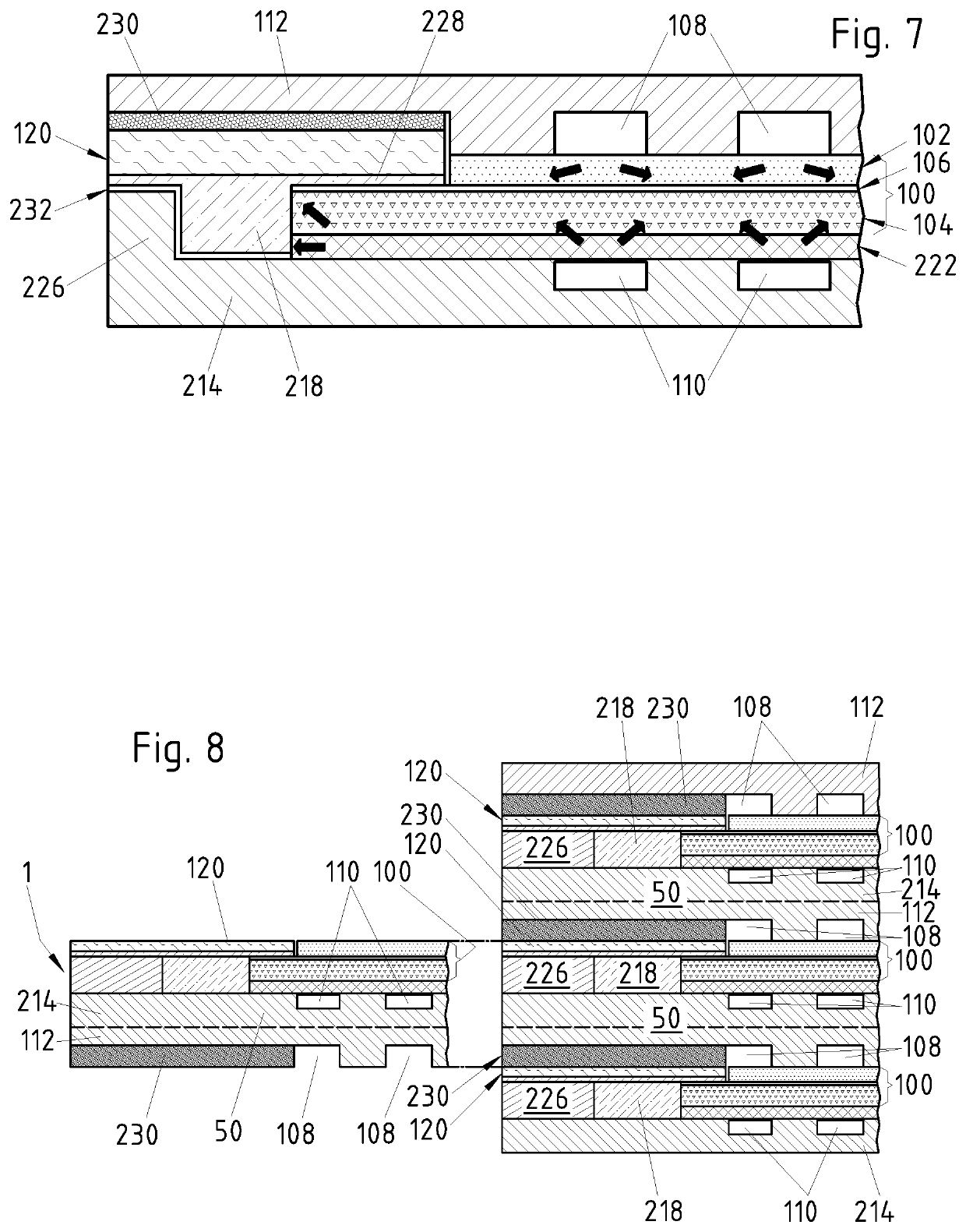
[0045]The planar arrangements forming the stack shown in FIG. 8 correspond to the same seventh embodiment also shown in FIG. 7. It should be understood however that any embodiment of the invention can be adapted to form the stacking units of a stack. Conversely, the high temperature planar electrochemical cell of any one of the planar arrangements illustrated in FIGS. 1 to 7 can also function on its own as an individual electrochemical reactor. In this second case, the two interconnects both belong to the one and only SOFC. In this second case, an essential role played by the interconnects is that of current collectors.

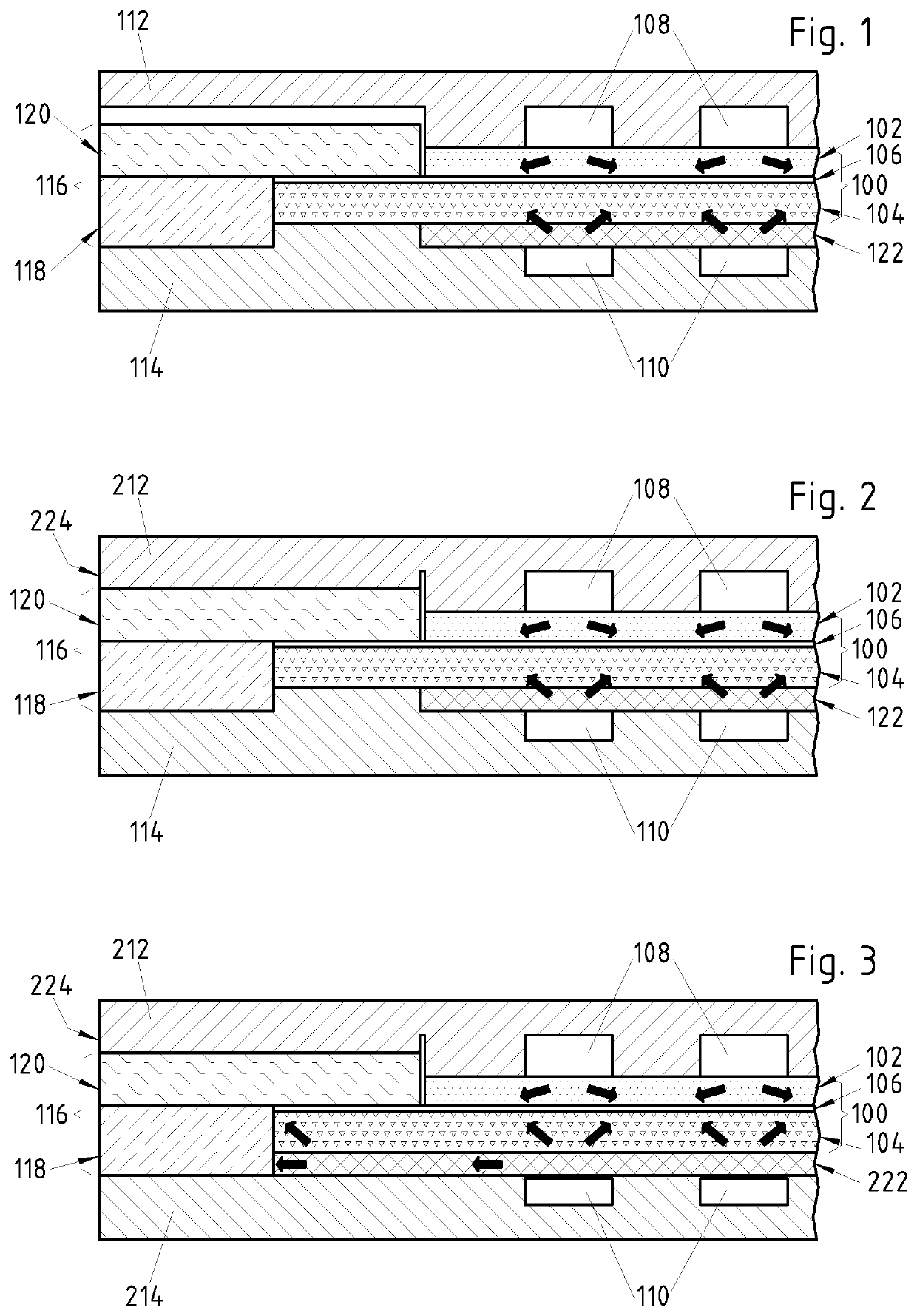
[0046]Now referring to FIG. 1 in particular, it can be observed that a contacting layer 122 is intercalated between the anode 104 and the surface of the second interconnect 114. The contacting layer 122 can be implemented for instance in the form of a layer of metal mesh that is arranged so as to cover the surface of the interconnect at least in the electrochemically ...

first embodiment

[0050]FIG. 1 further shows that, in this first embodiment, the glass layer 118 is formed over the periphery of the inner (or upper) surface of the second interconnect 114, and that it is arranged alongside the edge of the solid electrolyte layer 106, adjacent to it. It can further be observed in FIG. 1 that the top surface of the glass layer 118 is substantially flush with the top surface of the solid electrolyte layer 106, and that the mica sheet 120 that covers the glass layer also covers the peripheral part of the solid electrolyte layer. Furthermore, the mica sheet borders the edge of the cathode layer 102, in such a way as to substantially surround the cathode electrode. One advantage of the arrangement that has just been described is that the presence of the mica sheet helps to keep the oxidizing gas away from the glass component 118, and significantly limits the number of oxidizing gas molecules that can reach the glass component and diffuse into it.

[0051]Still referring to F...

fourth embodiment

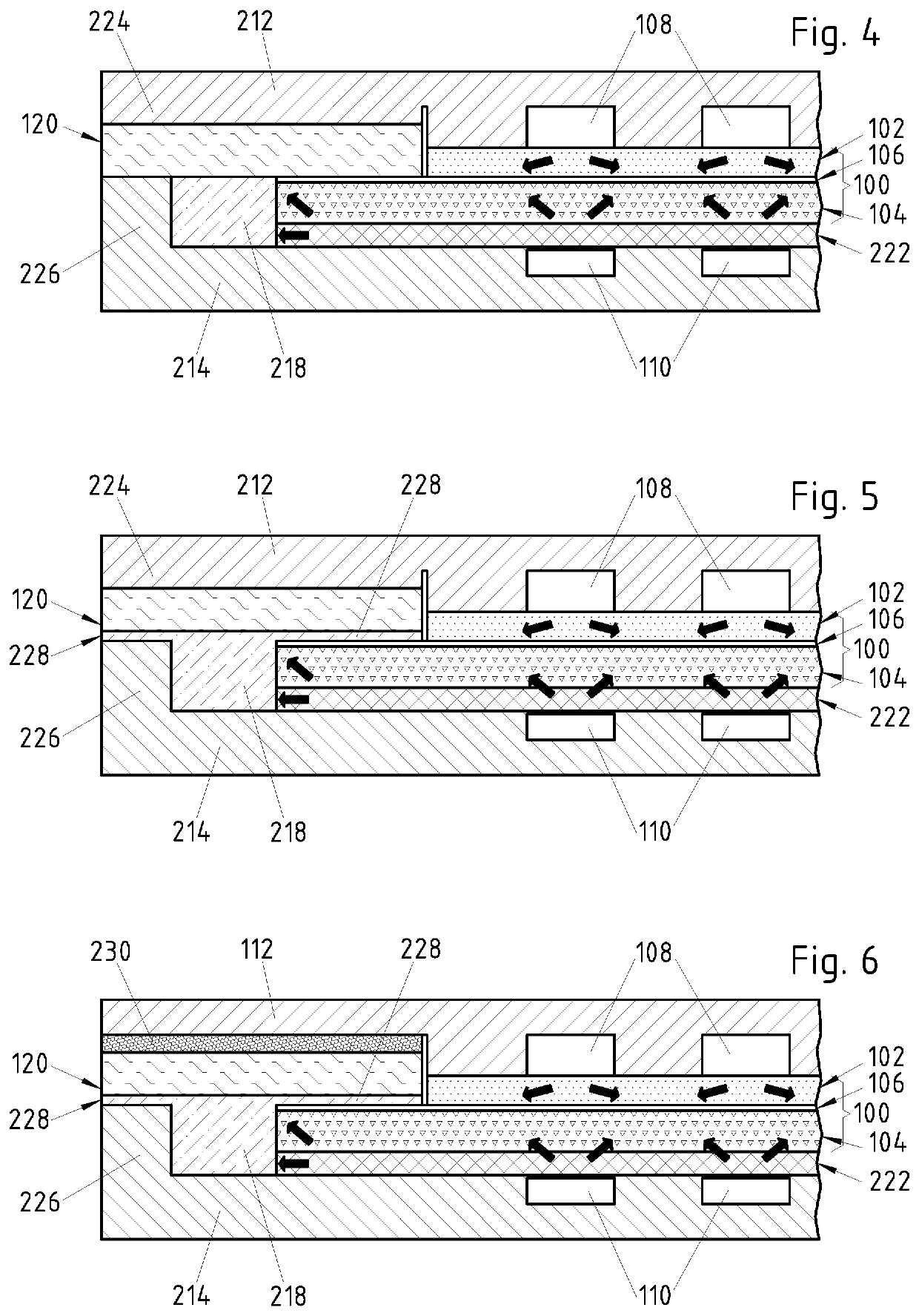
[0055]An advantage of the protruding part 226 of the present example is that it can constrain the glass component 218 during curing. In other words, it serves as a barrier to prevent the glass from flowing out when the viscosity of the glass component is low. Another advantage is that the protruding part 226 can itself improve the sealing functionality by operating as an additional barrier against gas flow. Furthermore, according to a preferred variant of the fourth embodiment, the top surface of the protruding part 226 is located in the same plane as the top surface of the solid electrolyte 106, and the mica sheet 120 also covers the protruding part. In this way, the protruding part can provide additional mechanical support for the mica sheet 120. An advantage of this arrangement is that it reduces to a minimum the stress and the strain on the mica sheet.

[0056]It should be understood however that, according to possible alternative embodiments (not shown), the upper surface of the s...


PUM

PropertyMeasurementUnit
temperatureaaaaaaaaaa
temperaturesaaaaaaaaaa
temperatureaaaaaaaaaa

Abstract

The planar arrangement having CAE-unit, both a first flow field for an oxidizing gas and a first interconnect arranged on a first side of the CAE-unit, both a second flow field for a combustible gas and a second interconnect arranged on the other side of the CAE-unit, the CAE-unit having a first and a second electrode layer, and a solid electrolyte sandwiched therebetween. The first electrode layer forming the first side of the CAE-unit and the second electrode layer forming the other side. Further including a circumferential sealing member to prevent either the leakage of oxidizing gas or combustible gas to the environment or the mixing of the two gases. The sealing member includes a glass component bound to the upper surface of the second interconnect, and a sheet of ceramic fiber paper or mica arranged so as to cover a side of the glass component facing the first interconnect.

Description

FIELD OF THE INVENTION[0001]According to a first aspect, the present invention is directed to a planar arrangement comprising at least one high temperature planar electrochemical cell comprising a first electrode layer, a second electrode layer, a solid electrolyte sandwiched between the first and the second electrode layer, both a first flow field for an oxidizing gas and a first interconnect comprising a current collector layer arranged on the same side of the solid electrolyte as the first electrode layer, both a second flow field for a combustible gas and a second interconnect comprising a current collector layer arranged on the same side of the solid electrolyte as the second electrode layer, and a circumferential sealing member provided in order to prevent the leakage of the oxidizing gas or of the combustible gas to the environment or to prevent any substantial mixing of said two gases. According to a second aspect, the invention is directed to a sealing member for a planar a...

Claims


Application Information

Patent Timeline
Patent Type & Authority Applications(United States)
IPC IPC(8): H01M8/1213H01M8/00H01M8/0258H01M8/2432C25B9/18H01M8/0276
CPCC25B9/18H01M8/0276H01M8/2432H01M8/1213H01M8/006H01M8/0258H01M2008/1293H01M8/0282Y02E60/50C25B9/70C25B9/73
Inventor WUILLEMIN, ZACHARIEANTONETTI, YANNIK
Owner SOLIDPOWER SA
Learn More