Video signal processor

a video signal and processor technology, applied in the field of video signal processors, can solve the problems of large increase in cost, prone to detection errors, and dot interference or cross-color interference, and achieve the effect of improving the image quality of a luminance signal and improving the detection accuracy of a motion of an imag

Active Publication Date: 2008-02-26
RAKUTEN GRP INC
View PDF5 Cites 10 Cited by
  • Summary
  • Abstract
  • Description
  • Claims
  • Application Information

AI Technical Summary

Benefits of technology

[0012]In view of the above-described problem, it is an object of the present invention to provide a video signal processor which can improve the detection accuracy of a motion of an image in a composite video signal and improve the image quality of a luminance signal and a color signal (color difference signal) separated from the composite video signal.
[0013]Further, it is another object of the present invention to provide a video signal processor which can selectively receive and process a composite video signal and a component video signal while minimizing an increase in a circuit scale or an increase in cost.
[0014]Furthermore, it is still another object of the present invention to provide a video signal processor which can remove an image quality debating component even if an input video signal is a component video signal including the image quality debating component while minimizing an increase in circuit scale or an increase in cost, and improve the image quality of the component video signal (or both the composite video signal and the component video signal).

Problems solved by technology

In the conventional video signal processor shown in FIG. 1, therefore, there is a problem that a detection error is apt to be generated in detection of a motion of an image.
In the conventional video signal processor shown in FIG. 1, the three-dimensional processing cannot be performed with respect to the component video signal including a dot interference component or a cross-color interference component, there is a problem that the dot interference or the cross-color interference is generated.
In the structure shown in FIG. 1, adding a circuit which also performs the three-dimensional processing with respect to the component video signal can remove the dot interference component or the cross-color interference component, but a circuit scale becomes large, which results in a great increase in cost.

Method used


Image

  • Video signal processor
  • Video signal processor
  • Video signal processor

Examples


first embodiment

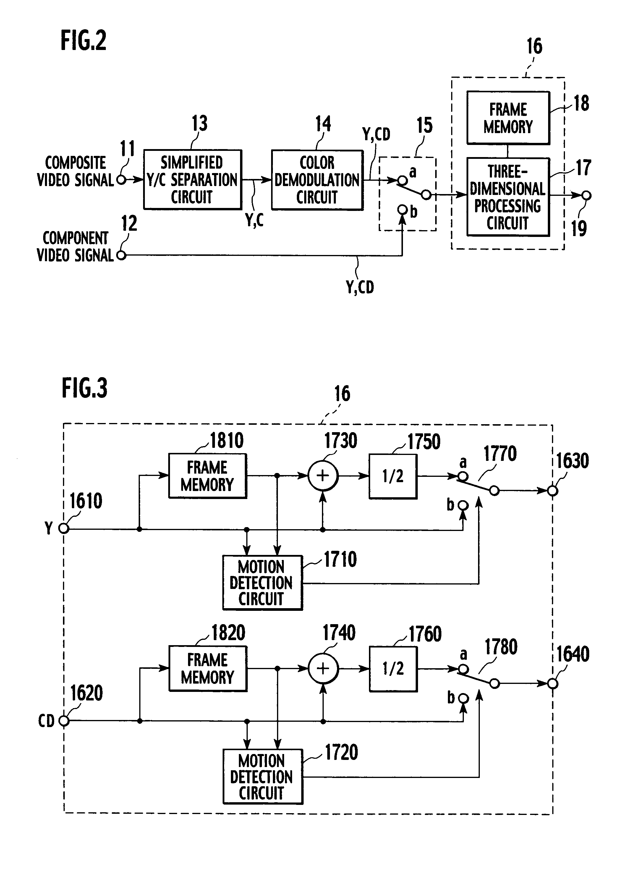
[0040]FIG. 2 is a block diagram showing a first embodiment of a video signal processor according to the present invention. FIG. 3 is a block diagram showing a concrete structural example of a three-dimensional processing portion 16 depicted in FIG. 2.

[0041]In FIG. 2, a composite video signal is input to an input terminal 11, and a component video signal is input to an input terminal 12. The composite video signal is input to a simplified Y / C separation circuit 13. The simplified Y / C separation circuit 13 is a Y / C separation circuit which does not include a frame memory (which does not perform three-dimensional processing), and it is, e.g., a band pass filter which extracts a chrominance subcarrier frequency (3.58 MHz in case of the NTSC mode) as a central band, a comb type filter using a line correlation, or a two-dimensional Y / C separation circuit. The simplified Y / C separation circuit 13 separates a Y signal and a C signal from each other in a simplified manner. The Y signal and t...

second embodiment

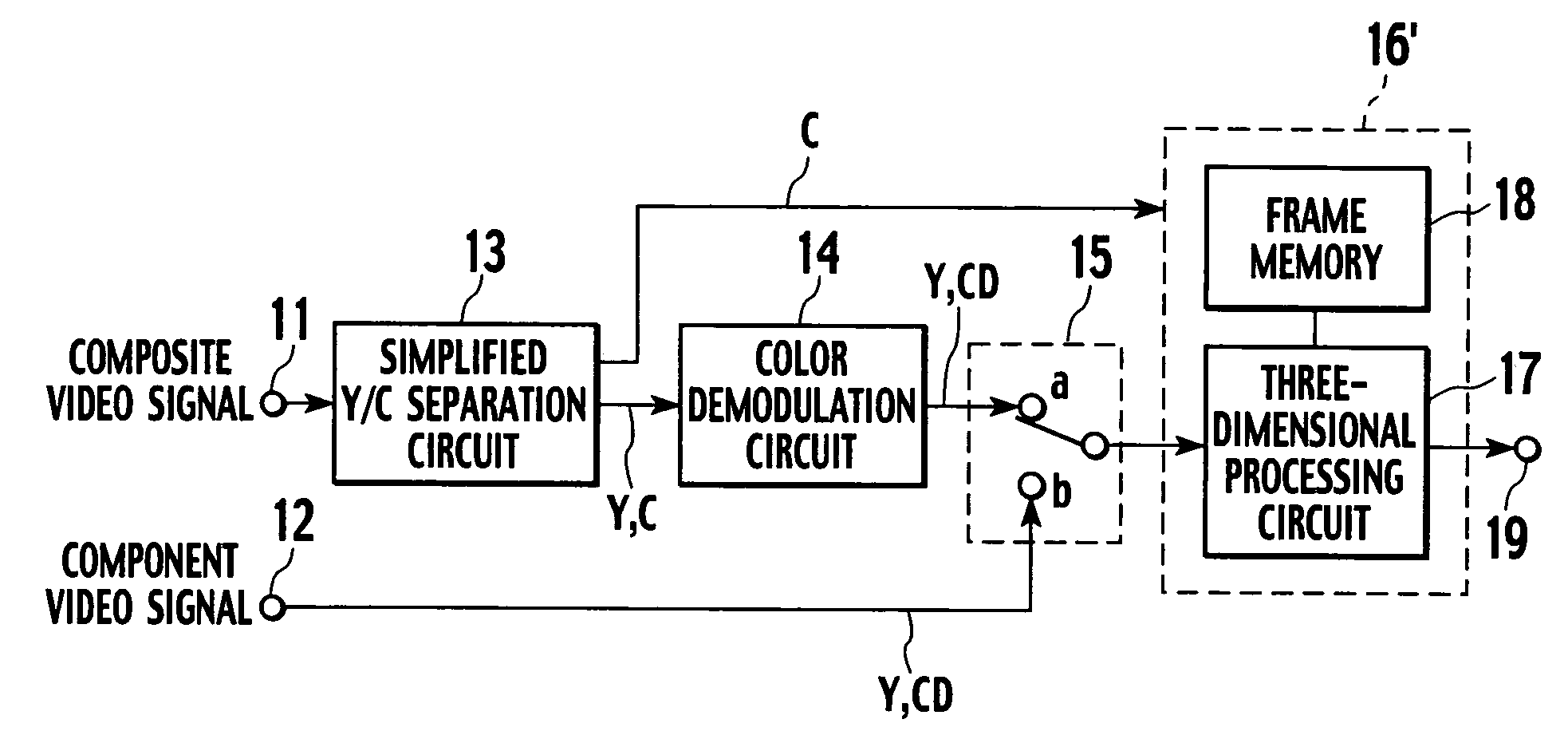
[0051]FIG. 4 is a block diagram showing a second embodiment of the video signal processor according to the present invention. FIG. 5 is a block diagram showing a concrete structural example of a three-dimensional processing portion 16′ in FIG. 4.

[0052]In the second embodiment shown in FIGS. 4 and 5, like reference numerals denote parts equal to those in the first embodiment shown in FIGS. 2 and 3, and the explanation thereof will be appropriately eliminated. As shown in FIG. 4, the second embodiment is characterized in that the C signal separated by the simplified Y / C separation circuit 13 is input to the three-dimensional processing portion 16′ in order to further improve the image quality of the Y signal. Specifically, as shown in FIG. 5, the C signal output from the simplified Y / C separation circuit 13 is input to an input terminal 1650, and a mixer 1790 mixes the Y signal input to the input terminal 1610 with the C signal input to an input terminal 1650, and supplies a result to...

third embodiment

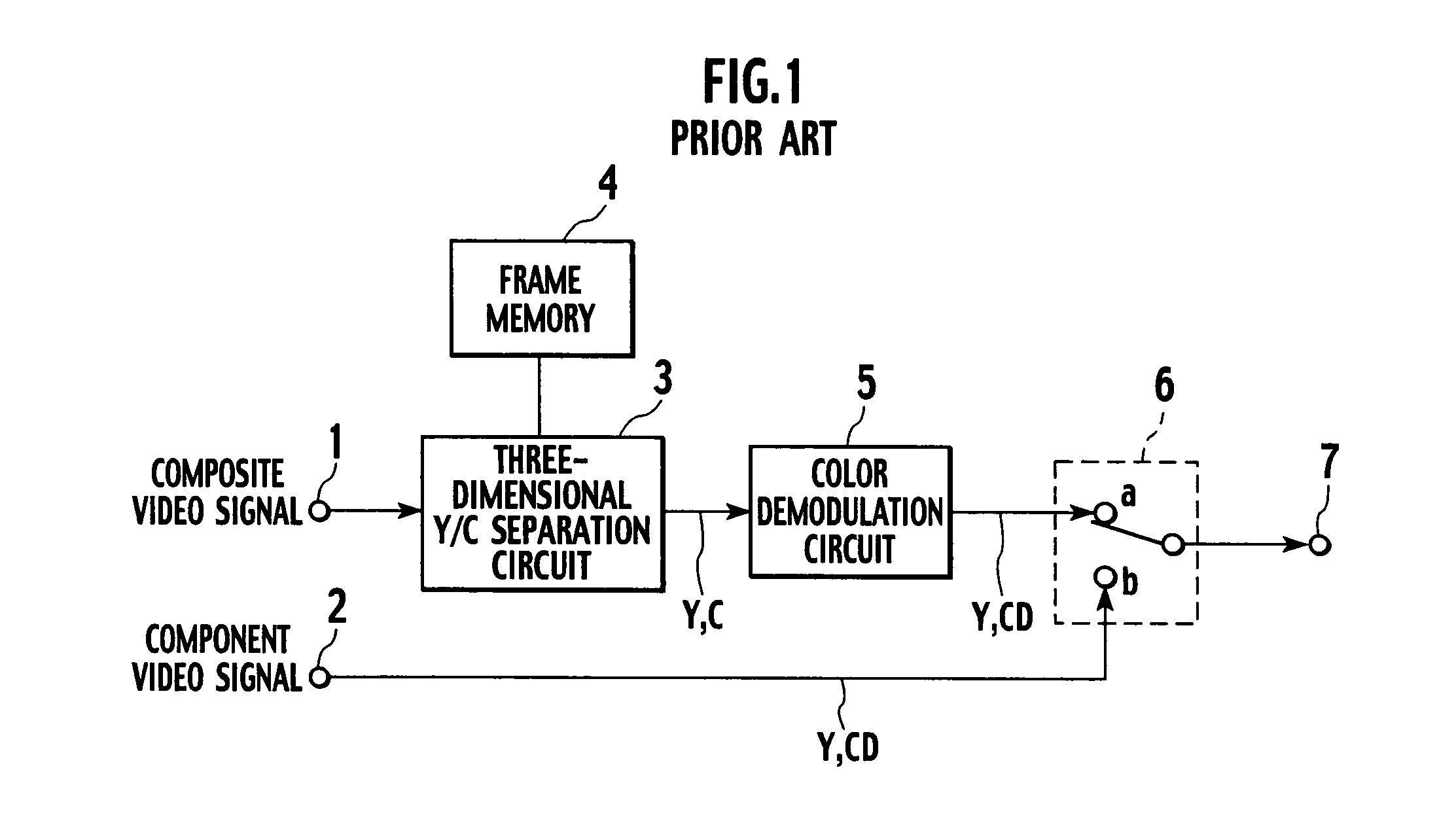
[0054]FIG. 6 is a block diagram showing a third embodiment of the video signal processor according to the present invention.

[0055]Although the first and second embodiments mentioned above perform the three-dimensional processing by using the three-dimensional processing portion 16 even if a processing target is the component video signal, the third embodiment shown in FIG. 6 is configured not to perform the three-dimensional processing with respect to the component video signal which does not include a dot interference component or a cross-color interference component. It is preferable to switch the processing in such a manner that the three-dimensional processing is performed with respect to the component video signal which may possibly include a dot interference component or a cross-color interference component as described above but the three-dimensional processing is not carried out with respect to the component video signal which is considered not to include the dot interferenc...


PUM


Abstract

A simplified Y / C separation circuit separates a composite video signal into a first luminance signal and a first color signal without subjecting the composite video signal to three-dimensional processing. A color demodulation circuit color-demodulates the first color signal into a first color difference signal. A three-dimensional processing portion removes an image quality debasing component by performing three-dimensional processing with respect to the first luminance signal and the first color difference signal or a second luminance signal constituting a component video signal and a second color difference signal. A selector selectively supplies the first luminance signal and the first color difference signal or the second luminance signal and the second color difference signal to the three-dimensional processing portion.

Description

BACKGROUND OF THE INVENTION[0001]1. Field of the Invention[0002]The present invention relates to a video signal processor which determines a composite video signal or a component video signal as an input video signal, and more particularly, it relates to a video signal processor which can remove an image quality debasing component in a composite video signal and a component video signal to improve the image quality.[0003]2. Description of the Related Art[0004]As video signals to be input to an image display apparatus, there are a composite video signal, such as an NTSC signal or a PAL signal, in which a luminance (Y) signal is composed with a color (C) signal, and a component video signal in which a luminance signal is separated from a color signal or a color difference signal. When a composite video signal is determined as an input video signal, a luminance signal and a color signal must be accurately separated from each other or else a dot interference by which a color signal comp...

Claims


Application Information

Patent Timeline
Patent Type & Authority Patents(United States)
IPC IPC(8): H04N9/77H04N9/78H04N9/64
CPCH04N9/641H04N9/78
Inventor SUZUKI, MAKIKOHASEGAWA, JUNICHI
Owner RAKUTEN GRP INC
Why Eureka
Try Eureka