Container for bulk handling of fluids

a container and container technology, applied in the field of palletized shipping containers, can solve the problems of affecting the the damage of the container, so as to facilitate optimal emptying of the container, minimize shock, vibration and abrasive forces, and prevent the effect of sagging the bag

Inactive Publication Date: 2008-03-04
MILLAN BOX
View PDF21 Cites 32 Cited by
  • Summary
  • Abstract
  • Description
  • Claims
  • Application Information

AI Technical Summary

Benefits of technology

[0025]It is another object of this invention to provide a new and improved container for shipping liquids that has a separate corrugated intermediate liner to protect an internal bag from abrasive contact with the surface, corners and seams on the inner surface of an outer rigid shell.
[0028]Another object of this invention is to provide a new and improved shipping container for fluids wherein the fluid is enclosed within a flexible bag which is positioned within an outer shell, an intermediate corrugated liner is disposed between the bag and the outer shell, and the bag has a non-removable top bung releasably supported on a top wall of the liner to maintain the bung in a proper position and prevent the top of the bag from sagging.
[0029]A further object of this invention is to provide a new and improved shipping container for fluids having an inwardly and downwardly angled cushioning drain surface for supporting the bottom of the intermediate liner and flexible bag which facilitates optimal emptying of the bag, significantly reduces the amount of residual material remaining in the bag, and provides an additional cushioning support surface for the fluid filled bag.
[0030]A still further object of this invention is to provide a new and improved palletized shipping container for shipping bulk liquids that has an internal collapsible bag fitted within a rigid outer container shell having a pallet structure configured to allow entry of the forks of a fork lift from any of four sides to allow better access for lifting and handling and significantly reduce the likelihood of damage, spillage or leakage due to accidentally dropping a filled container.
[0032]The above noted objects and other objects of the invention are accomplished by a palletized shipping container having a multiple layer flexible, collapsible bag positioned to closely fit within inner surfaces of a rigid box-like outer container or shell. The bag has flap-like extensions at an upper end for attachment to the shell to maintain the bag in an erect uncollapsed configuration, a non-removable bung at its top end for either filling or discharge and a non-removable discharge valve adjacent the bottom of one of its side walls. An intermediate liner formed of non-abrasive corrugated material is sandwiched between the bag and the outer walls of the rigid container for protecting the bag and minimizing shock, vibration and abrasive forces on the bag. The bung is releasably retained at the top of the liner to maintain the bung in a proper position and prevent sagging of the bag. A cushioning inwardly and downwardly angled drain surface is disposed at the bottom of the shell for supporting the bottom of the liner and bag to facilitate optimal emptying of the bag, significantly reduce the amount of residual material remaining in the bag, and provide an additional cushioning support surface for the fluid filled bag. The pallet structure is permanently attached to the outer shell and is configured to allow entry of the forks of a fork lift from any of four sides to allow better access for lifting and handling and significantly reduce the likelihood of damage, spillage or leakage due to accidentally dropping a filled container.

Problems solved by technology

Containerized fluids experience severe handling forces such as vibrations, incline-impact, and droppage during shipment.
In the “bag-in-a-box” type of shipping containers, the outer walls of the enclosed bag are subjected to continuous and abrasive movement of the bag against the walls of the rigid container.
Such abrasion can result in bag breakage and leakage and resultant loss of contents and contamination of the surrounding area.
Removable valves and spouts are undesirable because of the need to keep track of separate parts.
Shipping of the valve and spout assembly parts is often done separately from the material, resulting in extra shipping costs, lost valves, incorrect fittings, broken pieces, and wasted time and effort.
Removable valve and spout assemblies also require the extra effort of attaching the spout and valve to the container before the removal of the material.
In addition, special tools may be needed for the attachment and removal of these assemblies, which creates a further hindrance.
Another problem with conventional “bag-in-a-box” type of shipping containers is that the floor of the outer shell or rigid container on which the collapsible inner bag is supported is flat and, thus, optimal emptying of the bag is difficult to achieve and residual material often remains in the bag.
Thus, access for lifting and handling is significantly limited and there is a likelihood of damage, spillage or leakage due to accidentally dropping a filled container.

Method used


Image

  • Container for bulk handling of fluids
  • Container for bulk handling of fluids
  • Container for bulk handling of fluids

Examples


Embodiment Construction

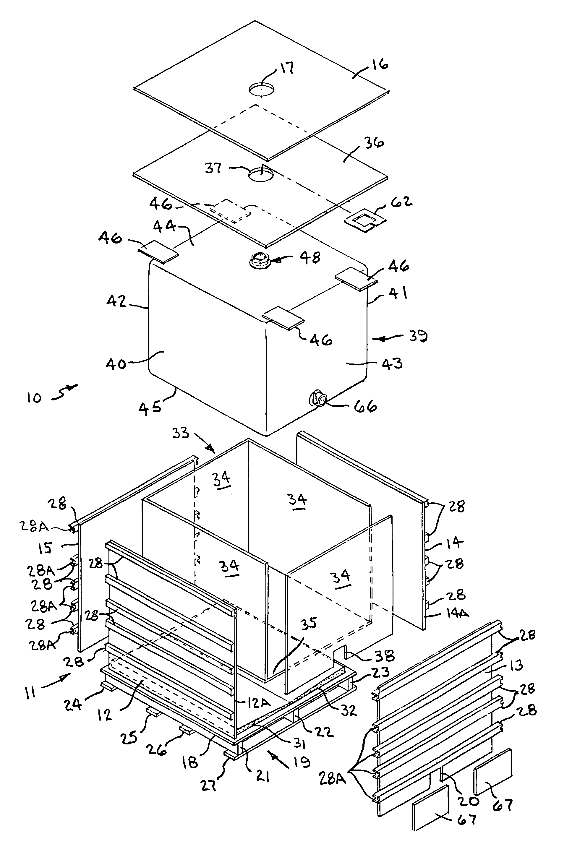
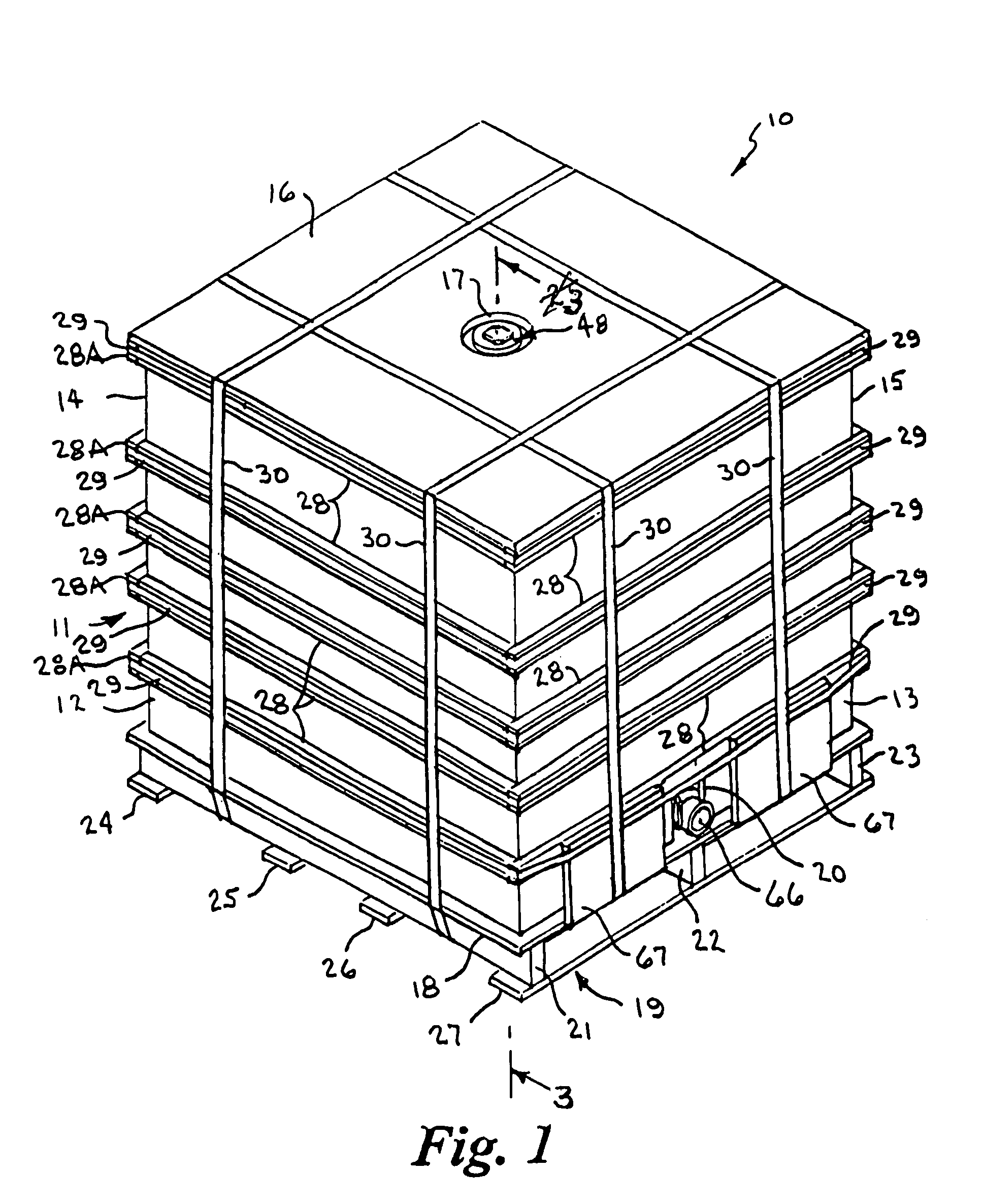
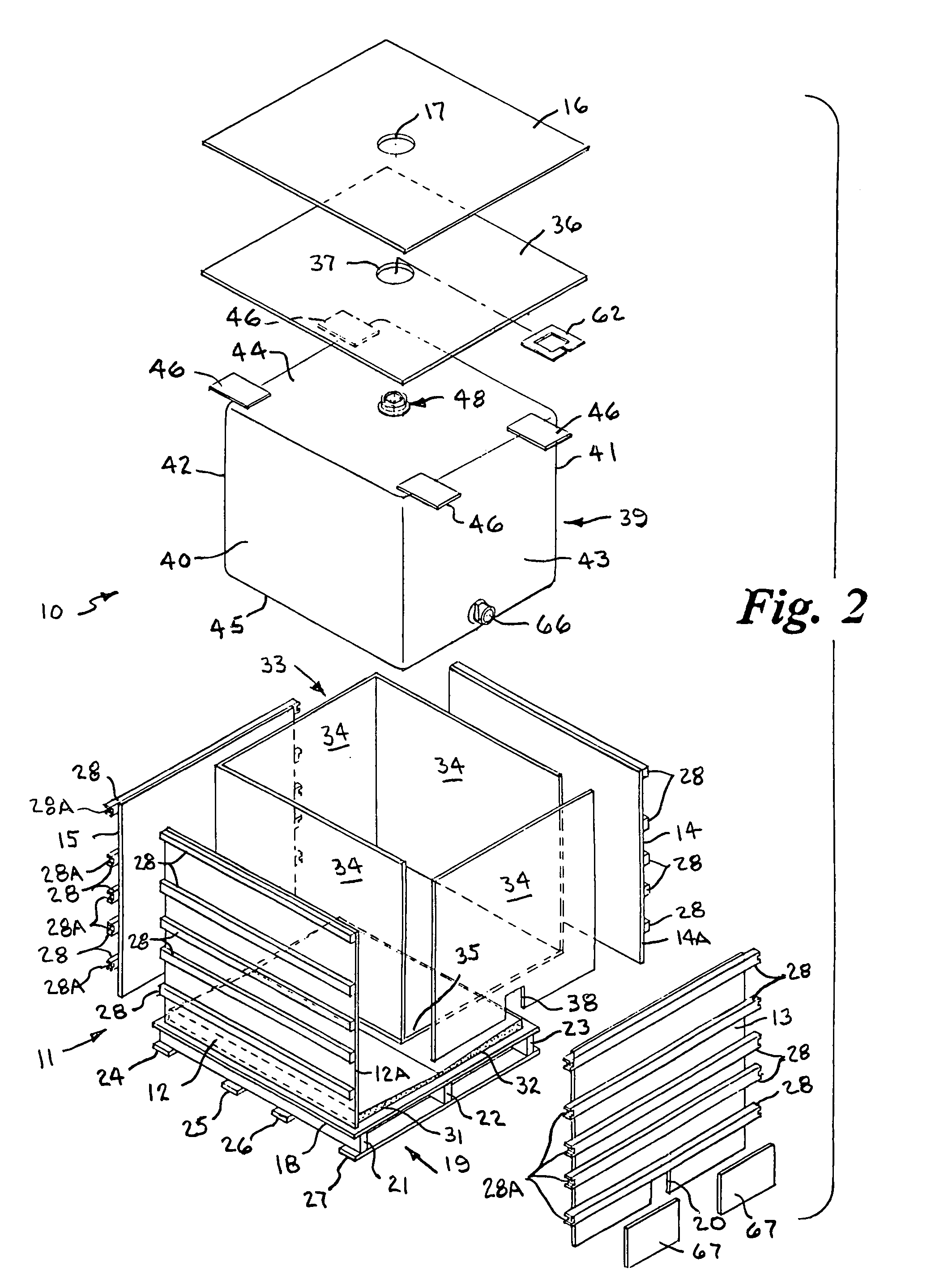
[0039]Referring to the drawings by numerals of reference, a preferred embodiment of a fully assembled shipping container 10 is shown in FIG. 1, and is shown exploded in FIG. 2 to reveal the principal elements, which include an outer rigid shell 11 with an integral pallet 19, a pair of support wedge members 31, 32 disposed inside the shell at the bottom thereof, an intermediate liner 33, and a flexible bag 39. The rigid outer shell 11 protects the inner bag 39 and its contents from blunt trauma and the integral pallet structure 19 permits individualized transportation and storage of the shell and its contents.

[0040]The outer shell 11 is constructed of four side walls 12, 13, 14 and 15, a top wall 16 with a circular hole 17 at the center thereof and a bottom wall 18 with an integral pallet 19. One of the side walls 13 is provided with a central generally rectangular opening 20 at its bottom end. The bottom wall 18 also serves as the pallet deck. The pallet 19 is formed by the deck (bo...


PUM


Abstract

A palletized shipping container for bulk handling of fluid materials has a rigid box-like outer shell within which is positioned a flexible bag and an intermediate corrugated liner sandwiched between the walls of the bag and shell. The bag has flap-like extensions at an upper end attached to the walls of the shell to maintain the bag in an erect uncollapsed configuration, a non-removable bung at its top end, and a non-removable discharge valve adjacent its bottom end. The bung is releasably retained at the top of the liner to maintain the bung in a proper position and prevent sagging of the bag. An inwardly and downwardly angled cushioned surface at the bottom of the shell supports the liner and bag, provides additional cushioning, facilitates emptying of the bag, and reduction of residual material. The pallet allows 4-sided entry of fork lift forks.

Description

BACKGROUND OF THE INVENTION[0001]1. Field of the Invention[0002]This invention relates generally to palletized shipping containers for bulk handling of fluent materials, and more particularly to palletized shipping containers having a collapsible bag encased in a strong outer shell for bulk handling of liquids, fine powders, granular products and other matter with flow characteristics.[0003]2. Background Art[0004]Containers and Intermediate Bulk Containers (IBC) are frequently used to ship, store, dispense, and handle liquids and other free flowing materials such as powders, pellets, etc. IBC's are also sometimes referred to as “totes”. IBC's typically hold more than a 55-gallon drum but less than bulk (500-gallon) containers. The most popular sizes are 275 gallon (equal to five 55-gallon drums) and 330 gallon (equal to six 55-gallon drums). Some IBC's are of a “bag-in-a-box” construction wherein a primary container in the form of a flexible collapsible inner bag actually contains t...

Claims


Application Information

Patent Timeline
Patent Type & Authority Patents(United States)
IPC IPC(8): B65D19/00
CPCB65D77/061
Inventor DEDMON, FRANKLIN
Owner MILLAN BOX
Why Eureka
Try Eureka